


5 - 9
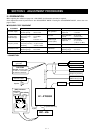
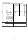
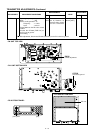
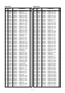
5-5 TRANSMITTER ADJUSTMENTS
The following adjustments must be performed at “ADJUSTMENT MODE” after “SWR DETECTOR” and “RECEIVER” ADJUST-
MENTS in the SECTION 5-3 and 5-4.
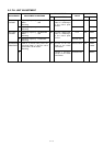
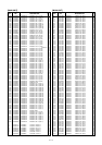
TRANSMIT
PEAK AND
TOTAL GAIN
(TX PEAK)
(TOTAL GAIN)
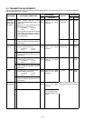
TX POWER
(HIGH)
(MIDDLE)
(LOW)
SWR
DETECTOR
1
2
1
2
1
2
1
2
1
2
• While pushing HM-146’s [CALL]
switch and RX-26’s [EMG] switch, turn
power ON.
• Connect an audio generator to the
[MIC] connector and set as:
Frequency : 1.5 kHz
Level : 3 mV
• Push [1] switch to enter the TX adjust-
ment mode
(LCD displayed: “TX SET”)
.
• Push [ENT] switch, then the transceiv-
er is transmitting.
• After setting 50 W, push the [OK]
switch to write the adjustment value in
the memory.
• LCD displayed :“TX POWER HIGH”
• Set the audio generator as:
Frequency : 1.5 kHz
Level : 30 mV
• After setting 88 W, push the [OK]
switch to write the adjustment value in
the memory.
• LCD displayed :“TX POWER MID”
• Set the audio generator as:
Frequency : 1.5 kHz
Level : 30 mV
• After setting 50 W, push the [OK]
switch to write the adjustment value in
the memory.
• LCD displayed :“TX POWER LOW”
• Set the audio generator as:
Frequency : 1.5 kHz
Level : 30 mV
• After setting 10 W, push the [OK]
switch to write the adjustment value in
the memory.
• LCD displayed :“SWR1.0”
• LCD displayed :”SWR2.0”
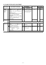
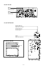
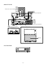
Rear
panel
Rear
panel
Rear
panel
Rear
panel
Rear
panel
Connect an RF power
meter to the [ANT]
connector.
Connect an RF power
meter to the [ANT]
connector.
Connect an RF power
meter to the [ANT]
connector.
Connect an RF power
meter to the [ANT]
connector.
Connect an RF power
meter to the [ANT]
connector.
Connect the 100 Ω
load (or SWR 2 dumy
load) to the [ANT] con-
nector.
Maximum out-
put power
50 W
88 W [AUS]
125 W [OTH]
50 W
10 W
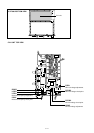
MAIN
RC-26
RC-26
RC-26
RC-26
L706
[VOL]
DIAL
[VOL]
DIAL
[VOL]
DIAL
[VOL]
DIAL
ADJUSTMENT ADJUSTMENT CONDITIONS
UNIT LOCATION
VALUE
UNIT ADJUST
MEASUREMENT ADJUSTMENT
• Push the [OK] switch to write the
adjustment value in the memory.