


5 - 7
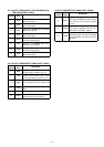
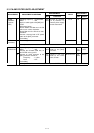
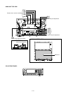
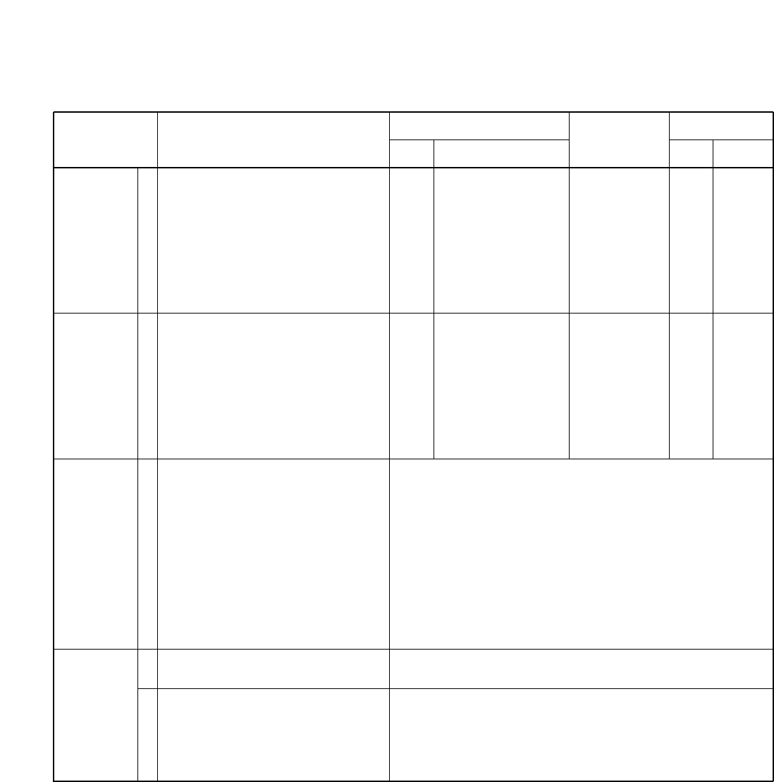
5-4 RECEIVER ADJUSTMENTS
”TOTAL GAIN”, “S-METER” and “DSC PEAK” adjustments must be performed at “ADJUSTMENT MODE”.
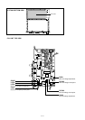
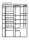
NOISE NULL
POINT
RECEIVER
GAIN
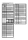
TOTAL GAIN
S-METER
1
1
1
1
2
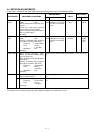
• Operating frequency : 0.5 MHz
• Mode : A3E
• Preset L209 parallel to top edge of its
chassis.
• Preset L401, L403, L404, L405 and
L801 to max. counter clockwise.
• Set the standard signal generator to
OFF (no signal output).
• Receiving
• Operating frequency : 13.9210 MHz
• Mode : J3E
• Connect a standard signal generator
to the [ANT] connector and set as:
Frequency : 13.9210 MHz
Level : 0.5 µV*
(–113 dBm)
Modulation : OFF
• Receiving
• While pushing HM-146’s [CALL]
switch and RC-26’s [EMG] switch,
then turn power ON.
• Push [2] switch to enter the RX adjust-
ment mode.
• Connect a standard signal generator
to the [ANT] connector and set as:
Frequency : 13.9210 MHz
Level : 320 µV*
(–57 dBm)
Modulation : OFF
• Receiving
• Set the standard signal generator to
OFF (no signal output).
• Set the standard signal generator as:
Frequency : 13.9210 MHz
Level : 10 mV*
(–27 dBm)
• Receiving
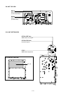
Front
panel
Front
panel
Connect an AC milli-
voltmeter to the [SP]
jack with a 4 Ω dummy
load.
Connect an AC milli-
voltmeter to the [SP]
jack with a 4 Ω dummy
load.
Minimum output
level
Maximum out-
put level
MAIN
MAIN
R217,
R218
L207,
L208,
L210,
L211
ADJUSTMENT ADJUSTMENT CONDITIONS
UNIT LOCATION
VALUE
UNIT ADJUST
MEASUREMENT ADJUSTMENT
*The output level of the standard signal generator (SSG) is indicated as the SSG’s open circuit.
• Push the [OK] switch to write the adjustment value in the memo-
ry.
• Push the [OK] switch to write the adjustment value in the memo-
ry.
• Push the [OK] switch to write the adjustment value in the memo-
ry.