


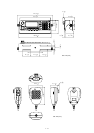
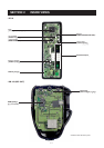
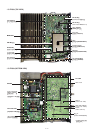
4 - 4
4-2-5 RF CIRCUIT (MAIN, PA, PLL UNITS AND DRI-
VER BOARD)
The RF circuit amplifies operating (transmitting) frequency
to obtain 100 W (125 W: 1.6–4 MHz for [OTH]) of RF output.
The RF signals from the 1st mixer circuit pass through the
low-pass filter (L702, L703, C706, C707, C709–C711,
C721), and are then applied to the RF amplifier (Q701).
The amplified signals pass through one of the low-pass filter
or bandpass filters (Refer to page 4-1 bandpass filters
used), and are then applied to the YGR amplifier (IC1, pin 1)
after being passed through the attenuator (R5–R7). The
amplified signals pass through the low-pass filter (L1–L3,
C1–C7) and attenuator (R1–R3), and are then applied to
the PA unit via J1.
The signals that applied from the MAIN unit are amplified at
2 amplifiers (PA unit; Q6101 and Q6801). A part of output
signals from 2 amplifiers are applied to these amplifiers to
improve the frequency characteristic by feedback. The
amplified signals are applied to the drive amplifier (DRIVER
board; Q6851) via the J6301 as “DRVI” signal. The signals
from the DRIVER board pass through the impedance con-
verter (PA unit; L6301), and then applied to push-pull ampli-
fiers (PA unit; Q6401, Q6402) to obtain a stable 100 W of RF
output power. A part of the RF output power returns to ampli-
fiers to obtain a stable gain between 1.6 MHz and 27.5 MHz
bands by using feedback transformer (L6404). The output
RF signals are applied to the filter unit via the J6401 as
“FLIN” signal.
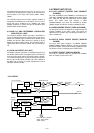
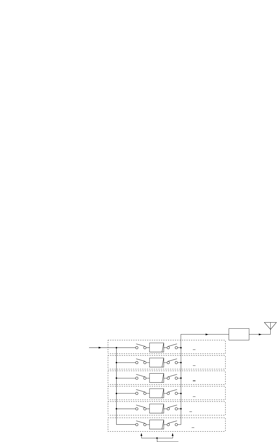
The amplified signals are applied to the one of the 6 low-
pass filters which are composed of chebychev type.
• 0.5–2.49999 MHz signals
The signals are applied to the relay (FILTER unit; RL7031).
The signals pass through the low-pass filter (FILTER unit;
L7036, L7037, C7033–C7036, C7038–C7040), and are then
applied to the RL7032 which is controlled by the band con-
trol IC (MAIN unit; IC3602) as the “L1M” signal via the buffer
amplifier (MAIN unit; IC1301, pin 13).
• 2.5–3.49999 MHz signals
The signals are applied to the relay (FILTER unit; RL7061).
The signals pass through the low-pass filter (FILTER unit;
L7067, L7068, C7072, C7073, C7077–C7083), and are then
applied to the RL7062 which is controlled by the band con-
trol IC (MAIN unit; IC3602) as the “L2M” signal via the buffer
amplifier (MAIN unit; IC1301, pin 14).
• 3.5–5.49999 MHz signals
The signal is applied to the relay (FILTER unit; RL7091). The
signals pass through the low-pass filter (FILTER unit; L7096,
L7097, C7094–C7099, C7105–C7107), and are then
applied to the RL7092 which is controlled by the band con-
trol IC (MAIN unit; IC3602) as the “L4M” signal via the buffer
amplifier (MAIN unit; IC1301, pin 15).
• 5.5–8.9999 MHz signals
The signals are applied to the relay (FILTER unit; RL7121).
The signals pass through the low-pass filter (FILTER unit;
L7127, L7128, C7123, C7126–C7131), and are then applied
to the RL7122 which is controlled by the band control IC
(MAIN unit; IC3602) as the “L6M” signal via the buffer ampli-
fier (MAIN unit; IC1301, pin 16).
• 9–14.9999 MHz signals
The signals are applied to the relay (FILTER unit; RL7181).
The signals pass through the low-pass filter (FILTER unit;
L7183, L7184, C7183–C7188, C7193–C7196), and are then
applied to the RL7182 which is controlled by the band con-
trol IC (MAIN unit; IC3602) as the “L12M” signal via the
buffer amplifier (MAIN unit; IC1301, pin 17).
• 15–29.9999 MHz signals
The signals are applied to the relay (FILTER unit; RL7241).
The signals pass through the low-pass filter (FILTER unit;
L7245, L7246, C7243–C7245, C7247, C7248, C7253), and
are then applied to the RL7242 which is controlled by the
band control IC (MAIN unit; IC3602) as the “L22M” signal via
the buffer amplifier (MAIN unit; IC1301, pin 18).
The filtered signal is applied to the antenna connector after
being passed through the RL7301 and J7211.
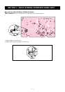
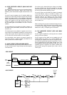
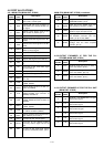
Antenna
power
detector
LPF
LPF
Filter: L0
0.5 2.4999 MHz
Filter: L1
2.5 3.4999 MHz
Filter: L2
3.5 5.4999 MHz
Filter: L3
5.5 8.9999 MHz
Filter: L4
9—14.9999 MHz
Filter: L5
low-pass filter control signals
from the MAIN unit
15—29.9999 MHz
LPF
LPF
LPF
LPF
(L1M, L2M, L4M, L6M, L12M, L22M)
Transmitter signals
from the PA unit.
• RF FILTER CIRCUIT