


4 - 5
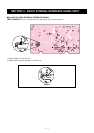
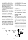
4-2-6 ALC CIRCUIT (PLL AND MAIN UNITS)
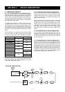
The ALC (Automatic Level Control) circuit controls the gain
of IF amplifiers in order for the transceiver to output a con-
stant RF power even when the supplied voltage shifts, etc.
The RF power level is detected at the power detector circuit
(PLL unit; D7271) to be converted into DC voltage and
applied to the MAIN unit as the “FOR” signal.
The “FOR” signal is applied to the comparator (IC1201, pin
2). The “POCV” signal is also applied to the other input (pin
3) for reference. The compared signal is output from pin 1
and applied to the IF amplifier in the MAIN (Q801) unit to
control amplifying gain.
When the “FOR” signal exceeds the “POCV” voltage, ALC
bias voltage from the comparator controls the IF amplifiers.
This adjusts the output power to a specified level until the
“FOR” and “POCV” voltages are equalized.
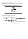
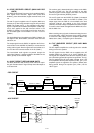
4-2-7 APC CIRCUIT (PLL AND MAIN UNITS)
The APC (Automatic Power Control) circuit protects the
power amplifiers on the PA unit from high SWR and exces-
sive current.
• SWR APC CIRCUIT (PLL AND MAIN UNITS)
The reflected wave signal appears and increases on the
antenna connector. When the antenna is mismatched,
D7272 of the power detector circuit (D7271, D7272, L7272)
in the PLL unit detects the signal and applies it to the ALC
amplifier (IC1201, pin 9) in the MAIN unit as “REF” signal.
The output signal decreases the bias voltage of the RF APC
amplifier to reduce the output power.
• CURRENT APC CIRCUIT (PA AND MAIN UNITS)
The power transistor current is detected from the different
voltage between both terminals of a 0.012 Ω resistor
(R6651) on the PA unit. The detected voltage is applied to
the differential amplifier (IC6501). When the current of the
final transistors is more than 30 A, the detected voltage is
applied to the APC amplifier controller (IC1201) in the MAIN
unit to reduce the gate-2 voltage of the IF amplifier (Q801)
and thus reduce the output power.
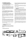
4-2-8 RF METER CIRCUIT (MAIN UNIT)
The output of ALC amplifier (IC1201, pin 14) is applied to the
CPU (IC3303, pin 97) as “RFML” signal to indicate the trans-
mit power level on the display.
For antenna current meter indication, the “ANTM” signal
from the optional AT-130E is applied to the meter amplifier
(IC1201, pin 12) via the J6701 in the PA unit.
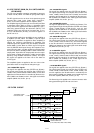
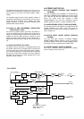
4-3 PLL CIRCUITS
4-3-1 GENERAL
The PLL circuits generate a reference frequency
(32.000 MHz); 1st LO frequencies (64.485–94.455 MHz);
2nd LO frequency (64 MHz), 3rd LO frequency
(422.500 kHz).
The 1st LO PLL adopts a mixer-less dual loop PLL system.
The BFO uses a DDS and a 2nd LO as a fixed frequency
double that the crystal oscillator.
4-3-2 1ST LO PLL (PLL UNIT)
The 1st LO PLL contains a main and reference loop as a
dual loop system.
The reference loop generates an approximate 10.5 MHz fre-
quency using a DDS circuit, and the main loop generates a
64.485 to 94.455 MHz frequency using the reference loop
frequency.
(1) REFERENCE LOOP PLL
The oscillated signal at the reference VCO (Q5301, D5301)
is amplified at the amplifiers (Q5302, Q5351) and is then
applied to the DDS IC (IC5101, pin 46). The signal is then
divided and detected on phase with the DDS generated fre-
quency.
The detected signal output from the DDS IC (pin 56) is con-
verted into DC voltage (lock voltage) at the loop filter
(R5136, R5146, C5112) and then fed back to the reference
VCO circuit (Q5301, D5301).
(2) MAIN LOOP PLL
The oscillated signal at one of the main loop VCOs (Q5521,
D5521, L5523) is amplified at the buffer amplifiers (Q5601,
Q5604) and is then applied to the PLL IC (IC5401, pin 6).
The signal is then divided and detected on phase with the
reference loop output frequency.
2
D7271
D7272
IC1201
9
1
8
LPF LPFs
BPFs
ALC
ALC amplifier
Antenna
FILTER UNITPA
UNIT
Power
detector
IF
ALC
Q801
TX
signals
Crystal
BPF
3rd mixer 2nd mixer 1st mixer
RF YGR PA
ALC
• ALC CIRCUIT