A. Specifications
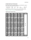
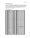
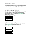
J12 (CompactFlash Connector)
J12 is a 50-pin, surface mount, right angle, CF card slot header (AMP 788667-1) designed
to accommodate a CompactFlash card. Refer to the CompactFlash Specification, Revision
1.X, for pinout and device information. For a copy of the most current specification and
more information about CompactFlash, visit the CompactFlash Association’s website at:
http://www.compactflash.org/
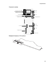
Refer to the “Connector Locations” figure to identify J12 on the ZT 4807.
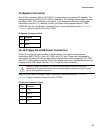
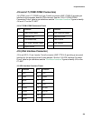
J13/J14 (Universal Serial Bus Connectors)
J13 and J14 are the rear-panel interface (AMP 440260-1) for the processor board's USB
Ports 0 and 1, respectively. J13 and J14 can be used simultaneously with the USB
connectors on the processor board's connector plate. See the “J13/J14 Universal Serial
Bus Connector Pinout” table for pin definitions and the “
Connector Locations” figure to
identify J13 and J14 on the ZT 4807.
J13/J14 Universal Serial Bus Connector Pinout
Pin Function
1 +5V (Fused)
2 DATA-
3 DATA+
4 Ground
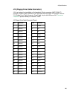
J15 (Keyboard/Mouse Connector)
J15 is a 6-pin DINN connector (AMP 749180-1) for standard PS/2 style keyboard and
Mouse devices. See the “J15 Keyboard/mouse Connector Pinout” table for pin definitions
and the “
Connector Locations” figure to identify J15 on the ZT 4807.
J15 Keyboard/Mouse Connector Pinout
Pin Function
1 Keyboard Data
2 Mouse Data
3 Ground
4 Switched +5V
5 Keyboard Clock
6 Mouse Clock
28


