A. Specifications
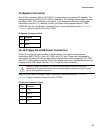
J16 and J17 (COM1/COM2 Connectors)
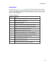
J16 (COM1) and J17 (COM2) are 9-pin D-shell connectors (AMP 179952-3) providing an
interface to the processor board’s COM channels. See the “J16/J17 COM1/COM2
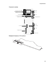
Connectors Pinout” table for pin definitions and the “
Connector Locations” figure to identify
J16 and J17 on the ZT 4807.
J16/J17 COM1/COM2 Connectors Pinout
Pin Function Pin Function
1 Data Carrier Detect 6 DCE (Data Set) Ready
2 Received Data 7 Request to Send
3 Transmitted Data 8 Clear to Send
4 DTE (Data Terminal) Ready 9 Ring Indicator
5 Signal Ground
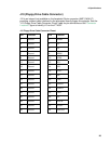
J19 (VGA Interface Connector)
J19 is an HD15, 15-pin, female, D-shell connector (AMP 177514-9) providing a rear-panel
interface for the processor board’s video adapter. See the “J19 VGA Interface Connector
Pinout” table for pin definitions and the “
Connector Locations” figure to identify J19 on the
ZT 4807.
J19 VGA Interface Connector Pinout
Pin Function Pin Function
1 RED 9 VCC
2 GRN 10 SGND
3 BLUE 11 N/C
4 N/C 12 SDA
5 DGND 13 HYSNC
6 RGND 14 VSYNC
7 GGND 15 SCL
8 BGND
29


