


Shower Base Installation And Operation www.jacuzzi.com Page 5
English
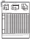
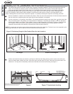
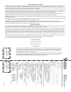
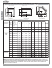
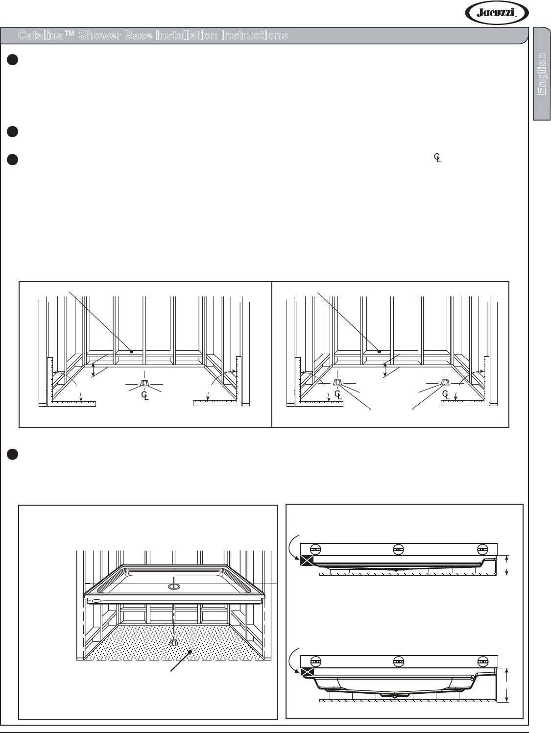
Figure 4 - Front to Back Leveling
(Left Hand And Right Hand Drain Models)
Figure 3 - Front to Back Leveling
(Center Drain Models)
Front of base*Height variation from 4-7/8 to 5-1/8”
Front of base
*Height variation from 4 to 4-3/4”
*4-3/16”
*5-1/8”
7/8” High Shim
Level
Level
1/2” High Shim
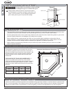
Catalina™ Shower Base Installation Instructions
Remove the shower base from the carton. Do not destroy the shipping carton until after satisfactory inspection of the
product. Should initial inspection reveal any damage or defect in the shower nish, do not install the shower base. Jacuzzi
®
Luxury Bath’s responsibility for shipping damage ceases upon delivery of the product in good order to the carrier. Refer any
claims of damage to the carrier. Any damage or defect claimed after installation is excluded from the warranty. Jacuzzi
is not responsible for any defect or damage that could have been discovered, repaired, or avoided by following this
inspection and testing procedure.
Plan the installation in relation to the nished wall surfaces. Take into account the dimensions of both the shower base and
the door enclosure. Install the optional trim parts after all other installation is completed.
Provide a minimum 5 x 5” opening in the suboor. The opening should be located on the center lines ( ) of the base drain
hole, see Product Chart. The opening is to acommodate a 2” waste pipe. The waste pipe should be 1/4 to 1/2” above the
surface of the suboor, see Figure 1. If the suboor is level, no other preparation is necessary. Proceed to install the base.
If the suboor is not level, level the shower base by spreading a oor-leveling compund, mortar, plaster, or minimal
expansion structural foam with a density of 5 pounds per cubic foot (lb/ft
³
) minimum.
NOTE: The compound must make contact with the entire bottom surface of the base feet. The base is not to be supported
by the base ange. Both sides of a joint or splice of sub-oor should be level to each other.
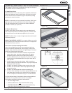
Position and install the base over the drain, see Figure 2. With the drain tting passing over the center of the drain pipe,
lower the shower base carefully into place. Push down rmly until the base is in place. Check the level of the base in two
directions. A high shim is necessary at the back of the base for front-to-back leveling (see Figures 3 & 4). Advance to page 7
to continue this installation procedure.
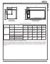
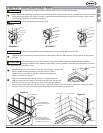
Center Drain Left Hand / Right Hand Drain
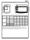
Figure 1. Preliminary Rough-in (See Product Chart for drain location)
90
o
90
*5½”
2 x 4” Blocking
*5½” from subfloor to top of blocking
90
o
90
o
2 x 4” Blocking
2” Waste Pipe
5 x 5” Opening (Max)
5 x 5”
Opening
(Max)
*4½” from subfloor to top of blocking
*4½”
2”
Waste
Pipe
Left Hand
Models
Right Hand
Models
o
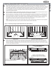
Spread mortar or leveling compound evenly over
the entire area. Lift and lower the base over the
center of the drain pipe and set it into place.
Figure 2
1
2
3
4