


21
ity of this kit, refer to the accessory ordering information inside the
back cover of this manual.
Bracket Installation
Recommended tools for this job include: drill, 1" (25.4 mm) drill bit, screw-
driver. Required supplies for this job include: high quality, marine grade
above- or below-waterline caulking compound, three #10 stainless steel
screws. Screw length and type should be suitable for the material on which
you intend to mount the bracket.
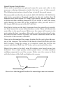
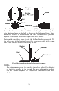
Mount the unit in any convenient location, provided there is clearance
when it’s tilted for the best viewing angle. You should also make sure
there is enough room behind the unit to attach the power/transducer
cable. (See the following drawings, which show the dimensions of a
gimbal-mounted X67C sonar unit.)
Holes in the bracket’s base allow wood screw or through-bolt mounting.
You may need to place a piece of plywood on the back side of thin pan-
els to reinforce the panel and secure the mounting hardware.
Drill a 1" (25.4 mm) hole in the dash for the power/transducer and ac-
cessory cables. The best location for this hole is immediately under the
gimbal bracket location. This way, the bracket can be installed so that
it covers the hole, holds the cables in position and results in a neat in-
stallation. Some customers, however, prefer to mount the bracket to the
side of the cable hole — it's a matter of personal preference.
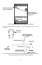
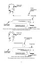
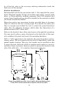
Front view (left) and side view (right) showing dimensions
of the X67C when mounted on quick release bracket.
Millimeter
[Inch]
82.7
[3.26]
12.09 [0.48]
107.5
[4.23]
76.9
[3.03]
156
[6.26]
70.3
[
2.77
]