


ENGLISH
5
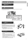
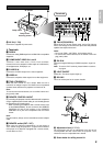
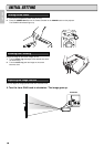
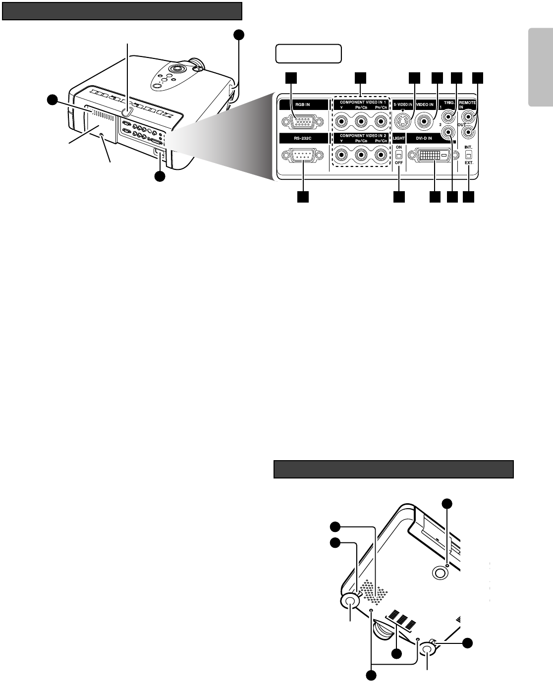
Rear and Terminals View
13
14
13
Lamp cover
securing screw
Lamp cover
IR sensor
1 2 3 4 5
11 9 8 7
6
10
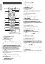
Terminals
!4 AC IN (
☞
P.8)
Connect the supplied AC power code.
❖ Terminals
z RGB IN
Connect the analog RGB output from an IBM VGA or compatible
equipment.
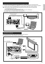
x COMPONENT VIDEO IN 1 and 2
Terminals 1 and 2 have each Y, PB/CB, PR/CR terminals.
Connect them to the component video output of a video device,
AV amp/processor, DVD player, etc.
c S-VIDEO IN
Connect the S-VIDEO output from a video equipment.
v VIDEO IN
Connect the composite video output from a video equipment.
b TRIG.1(TRIGGER 1)
When the unit is turned on, 12V is output. When the unit is
turned off, no voltage is output. This allows such as a powered
up/down screen,whenever the projector is turned on or off.
Note:
To connect with external devices, use an ordinal 3.5mm mini-
plug (mono) cable.
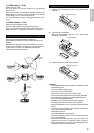
n REMOTE CONTROL IN/OUT
By connecting this projector to another Marantz audio component
using a supplied System Control cable, you can remotely operate
the components as a single system.
• When connecting to component with a remote sensor (such
as the SR9200,SR8200), be sure to connect the "REMOTE
CONTROL IN" jack of this projector to the "REMOTE
CONTROL OUT" jack of the component with the remote
sensor.
Note:
For connections, always use the included bus control adaptor
cable.
m REMOTE switch (EXT. / INT.)
When using this projector independently, set this switch to
"INT.". When using this projector in a system with a Marantz
DVD player or AV Receiver equipped with a remote sensor,
set the switch to "EXT.".
, TRIG.2(TRIGGER 2)
Select ON or OFF at each aspect mode, such as Full, Normal,
Zoom, and Through to control screen aspect ratio with powered
up/down dual aspect ratio screen.
Notes:
• Do not use TRIG.1 and TRIG.2, as the power source.
• To connect with external devices, use an ordinal 3.5mm mini-
plug (mono) cable.
. DVI-D IN
Connect the digital RGB signal (TMDS compliant, single link
only)
Note: To use the DVI-D terminal, please follow the cautions
on page 9.
⁄0 LIGHT ON/OFF
Select ON : The terminal panel lights up.
⁄1 RS-232C
This is the control port for the custom installer.
!5 Adjustment lever (
☞
P.11)
Lift the projector and turn the adjustment lever right or left.
The adjustable feet will extend from the projector. Then,
release the lever, the adjustable feet is locked.
!6 Screw holes for ceiling mount kit
15
13
13
16
15
16
Adjustable
feet
Adjustable feet
Bottom View