


10
GB
D
FINL EPGRRUTR
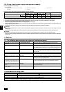
9. Additional refrigerant charge
At the time of shipping, the heat source unit is charged with the refrigerant. As this
charge does not include the amount needed for extended piping, additional charg-
ing for each refrigerant line will be required on site. In order that future servicing
may be properly provided, always keep a record of the size and length of each
refrigerant line and the amount of additional charge by writing it in the space pro-
vided on the heat source unit.
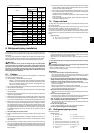
9.1. Calculation of additional refrigerant
charge
• Calculate the amount of additional charge based on the length of the piping
extension and the size of the refrigerant line.
• Use the table to the below as a guide to calculating the amount of additional
charging and charge the system accordingly.
• If the calculation results in a fraction of less than 0.1 kg [4 oz], round up to the
next 0.1 kg [4 oz]. For example, if the result of the calculation was 8.48 kg
[277.4 oz], round the result up to 8.5 kg [280 oz].
<Additional Charge>
• Flare machining dimension for systems using R410A is larger than that for
systems using other types of refrigerant in order to increase the air tightness.
• Refer to the table on the below for flare machining dimensions, and follow the
regulations set forth by the local authorities. Seal off the opening of the pipe
with a closure material (not supplied) to keep small animals from entering the
pipe if that is a concern.
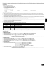
flare machining dimension (mm)
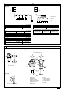
[Fig. 9.2.2] (P.3)
<A> [Ball valve (Gas side/flanged type)]
<B> [Ball valve (Liquid side/flared type)]
<C> This figure shows the valve in the fully open state.
A Valve stem
[Fully closed at the factory, when connecting the piping, when evacuating, and
when charging additional refrigerant. Open fully after the operations above are
completed.]
B Stopper pin [Prevents the valve stem from turning 90° or more.]
C Packing (Accessory)
[Manufacturer: Nichiasu corporation]
[Type: T/#1991-NF]
D Connecting pipe (Accessory)
[Use packing and securely install this pipe to the valve flange so that gas leakage
will not occur. (Tightening torque:40 N·m [400kg·cm]) Coat both surfaces of the
packing with refrigerating machine oil. (Ester oil, ether oil or alkylbenzene [small
amount])]
E Open (Operate slowly)
F Cap, copper packing
[Remove the cap and operate the valve stem. Always reinstall the cap after op-
eration is completed. (Valve stem cap tightening torque: 23 ~ 27 N·m [230 ~ 270
kg·cm])]
G Service port
[Use this port to evacuate the refrigerant piping and add an additional charge at
the site.
Open and close the port using a double-ended wrench.
Always reinstall the cap after operation is completed. (Service port cap tightening
torque: 12 ~ 15 N·m [120 ~ 150 kg·cm)]
H Flare nut
[Tightening torque: Refer to the following table.
Loosen and tighten this nut using a double-ended wrench.
Coat the flare contact surface with refrigerating machine oil (Ester oil, ether oil or
alkylbenzene [small amount])]
I ø9.52 [3/8] (PQHY-P72)
ø9.52 [3/8] (PQHY-P96)
J ø19.05 [3/4] (PQHY-P72)
ø22.2 [7/8] (PQHY-P96)
K Field piping
Appropriate tightening torque by torque wrench:
Copper pipe external dia. (mm [in]) Tightening torque (N·m / kg·cm)
ø6.35 [1/4] 14 to 18 / 140 to 180
ø9.52 [3/8] 35 to 42 / 350 to 420
ø12.7 [1/2] 50 to 57.5 / 500 to 575
ø15.88 [5/8] 75 to 80 / 750 to 800
ø19.05 [3/4] 100 to 140 / 1000 to 1400
Tightening angle standard:
Pipe diameter (mm [in]) Tightening angle (°)
ø6.35 [1/4], ø9.52 [3/8] 60 to 90
ø12.7 [1/2], ø15.88 [5/8] 30 to 60
ø19.05 [3/4] 20 to 35
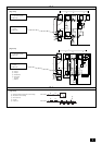
[Fig. 9.2.3] (P.3)
flare nut size (mm)
A
B
outer diameter
ø6.35
ø9.52
ø12.70
ø15.88
ø19.05
size in inches
1/4"
3/8"
1/2"
5/8"
3/4"
dimension A
R410A
9.1
13.2
16.6
19.7
24.0
outer diameter
ø6.35
ø9.52
ø12.70
ø15.88
ø19.05
size in inches
1/4"
3/8"
1/2"
5/8"
3/4"
dimension B
R410A
17.0
22.0
26.0
29.0
36.0
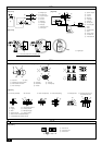
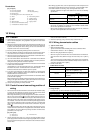
<Example>
Indoor 1: 24 A: ø9.52 [3/8] 40 m [131 ft] a: ø9.52 [3/8] 10 m [32 ft]
2: 36 B: ø9.52 [3/8] 10 m [32 ft] b: ø9.52 [3/8] 5 m [16 ft]
3: 15 C: ø9.52 [3/8] 15 m [49 ft] c: ø6.35 [1/4] 10 m [32 ft]
4: 12 D: ø9.52 [3/8] 10 m [32 ft] d: ø6.35 [1/4] 10 m [32 ft]
5: 24 e: ø9.52 [3/8] 10 m [32 ft]
The total length of each liquid line is as follows:
ø9.52 [3/8]: A + B + C + D + a + b + e = 40 [131] + 10 [32] + 15 [49] + 10 [32]
+ 10 [32] + 5 [16] + 10 [32]
= 100 m [292 ft]
ø6.35 [1/4]: c + d = 10 [32] + 10 [32] = 20 m [64 ft]
Therefore,
<Calculation example>
Additional refrigerant charge
= 100 [292] × 0.06 [0.65] + 20 [64] × 0.024 [0.26] + 2.0 [71] = 8.5 kg [280 oz]
Value of α
Total capacity of connecting indoor units α
Models 31 to 60 1.5 kg [53 oz]
Models 61 to 126 2.0 kg [71 oz]
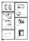
9.2. Precautions concerning piping connec-
tion and valve operation
• Conduct piping connection and valve operation accurately.
• Flange type side connecting pipe is assembled in factory before shipment.
1 For brazing to the connecting pipe with flange, remove the connecting pipe
with flange from the ball valve, and braze it outside of the unit.
2 During the time when removing the connecting pipe with flange, remove
the seal attached on the rear side of this sheet and paste it onto the flange
surface of the ball valve to prevent the entry of dust into the valve.
3 The refrigerant circuit is closed with a round, close-packed packing upon
shipment to prevent gas leak between flanges. As no operation can be
done under this state, be sure to replace the packing with the hollow pack-
ing attached at the piping connection.
4 At the mounting of the hollow packing, wipe off dust attached on the flange
sheet surface and the packing. Coat refrigerating machine oil (Ester oil,
ether oil or alkylbenzene [small amount]) onto both surfaces of the pack-
ing.
[Fig. 9.2.1] (P.3)
A Close-packed packing
B Hollow packing
• After evacuation and refrigerant charge, ensure that the handle is fully open. If
operating with the valve closed, abnormal pressure will be imparted to the
high- or low-pressure side of the refrigerant circuit, giving damage to the com-
pressor, four-way valve, etc.
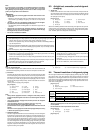
• Determine the amount of additional refrigerant charge by using the formula,
and charge refrigerant additionally through the service port after completing
piping connection work.
• After completing work, tighten the service port and cap securely not to gener-
ate gas leak.
At the
conditions
below:
=+++ α
Liquid pipe size
Total length of
ø6.35 [1/4]
(m) × 0.024 (kg/m)
(in) × 0.26 (oz/ft)
Liquid pipe size
Total length of
ø9.52 [3/8]
(m) × 0.06 (kg/m)
(in) × 0.65 (oz/ft)
Additional
refrigerant charge
(kg) [oz]
Liquid pipe size
Total length of
ø12.7 [1/2]
(m) × 0.12 (kg/m)
(in) × 1.29 (oz/ft)