


8
GB
D
FINL EPGRRUTR
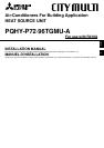
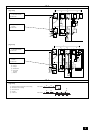
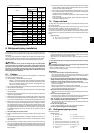
6. Installation of unit and service space
6.1. Installation
• Using the anchoring holes shown below, firmly bolt the unit to the base.
[Fig. 6.1.1] (P.2)
A Heat source unit B 4-ø14 [9/16] (Anchoring hole)
C (Top view)
Bases and anti-vibration
• Be sure to install unit in a place strong enough to withstand its weight. If the
base is unstable, reinforce with a concrete base.
• The unit must be anchored on a level surface. Use a level to check after
installation.
• Anti-vibration pads must be placed under the base of the unit.
• If the unit is installed near a room where noise is a problem, using an anti-
vibration stand on the base of the unit is recommended.
[Fig. 6.1.2] (P.2)
D Anti-vibration pad etc. E Concrete base
Warning:
• Be sure to install unit in a place strong enough to withstand its weight.
Any lack of strength may cause unit to fall down, resulting in a personal
injury.
• Have installation work in order to protect against earthquake.
Any installation deficiency may cause unit to fall down, resulting in a
personal injury.
6.2. Service space
• Please allow for the following service spaces after installation.
(All servicing can be performed from the front of the unit)
[Fig. 6.2.1] (P.2)
A Piping space (for side piping) B Heat source unit
C Service space (front side) D (Top view)
[Fig. 6.2.2] (P.2)
E Piping space (for top piping) F Piping space (for side piping)
G Heat source unit H (Front view)
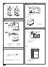
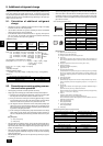
5. Lifting method
[Fig. 5.0.1] (P.2)
Caution:
Be very careful when carrying the product.
- Do not have only one person to carry product if it is more than 20 kg [46 LBS].
- PP bands are used to pack some products. Do not use them as a mean for transportation because they are dangerous.
- Tear plastic packaging bag and scrap it so that children cannot play with it. Otherwise plastic packaging bag may suffocate children to death.
- When carrying the heat source unit, be sure to support it at four points. Carrying with 3-point support may make the heat source unit unstable, resulting in it falling.
4. Confirmation of parts attached
1 Connecting pipe × 1 (Connecting pipe is fixed with the unit.) 2 Packing (inside ø23 [29/32 in], outside ø35 [1-13/32 in]) × 1
3 Bushing × 2
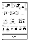
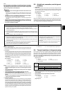
7. Water pipe installation
• City Multi WY Series pipes are similar to other air-conditioning pipes, however,
please observe the following precautions during installation.
7.1. Precautions during installation
• Use the reverse-return method to insure proper pipe resistance to each unit.
• To insure easy maintenance, inspection, and replacement of the unit, use a
proper joint, valve, etc. on the water intake and outlet port. In addition, be sure
to install a strainer on the water intake pipe. (In order to maintain the heat
source unit, a strainer on the circulating water inlet is necessary.)
* An example of the heat source unit installation is shown in the diagram be-
low.
• Install a suitable air vent on the water pipe. After sending water through the
pipe, be sure to vent the excess air.
• Compressed water may form in the low-temperature sections of heat source
unit. Use a drainage pipe connected to the drain valve at the base of the unit to
drain the water.
• There is a water vent plug in the center of the heat exchanger water inlet head
at the middle of the unit. Use this for maintenance, etc.
In addition, do not allow any of the unit’s electrical parts (such as the solenoid
valve coil or compressor power supply) to become wet.
• Install a back flow-prevention valve on the pump and a flexible joint to prevent
excess vibration.
• Use a sleeve to protect the pipes where they go through a wall.
• Use metal fittings to secure the pipes, and install them so that they have maxi-
mum protection against breakage and bending.
• Do not confuse the water intake and outlet valves.
• This unit doesn’t have any heater to prevent freezing within tubes. When the
water flow is stopped on low ambient, take out the water from tubes.
• The unused knockout holes should be closed and the opening of refrigerant
pipes, water pipes, power source and transmission wires should be filled with
putty and so on to prevent from rain. (field construction)
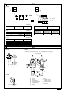
Example of heat source unit installation (using left piping)
[Fig. 7.1.1] (P.2)
A Water circulation pipe B Close valve
C Close valve D Water outlet
E Refrigerant piping F Y-type strainer
G Water inlet H Drain pipe
7.2. Insulation installation
With City Multi WY Series piping, as long as the temperature range of the circulat-
ing water is kept to average temperatures year-round (30 °C [86 °F] in the summer,
20 °C [68 °F] in the winter), there is no need to insulate or otherwise protect indoor
piping from exposure. You should use insulation in the following situations:
• Any heat source piping.
• Indoor piping in cold-weather regions where frozen pipes are a problem.
• When air coming from the outside causes condensation to form on piping.
• Any drainage piping.
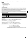
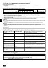
7.3. Water processing and water quality con-
trol
To preserve water quality, use the closed type of cooling tower for WY. When the
circulating water quality is poor, the water heat exchanger can develop scales,
leading to a reduction in heat-exchange power and possible corrosion of the heat
exchanger. Please pay careful attention to water processing and water quality control
when installing the water circulation system.
• Removal of foreign objects or impurities within the pipes.
During installation, be careful that foreign objects, such as welding fragments,
sealant particles, or rust, do not enter the pipes.
• Water Quality Processing
1 Depending on the quality of the cold-temperature water used in the air-
conditioner, the copper piping of the heat exchanger may become corroded.
We recommend regular water quality processing.
Cold water circulation systems using open heat storage tanks are
particularly prone to corrosion.
When using an open-type heat storage tank, install a water-to-water heat
exchanger, and use a closed-loop circuit on the air conditioner side. If a
water supply tank is installed, keep contact with air to a minimum, and
keep the level of dissolved oxygen in the water no higher than 1mg/r.