


5
A B C
E
D
M1 M2
M1 M2 S
TB7
TB3
IC
(51)
M1 M2 S
TB5
RC
(01)
IC
M1 M2 S
TB5
(02)
IC
M1 M2 S
TB5
(04)
IC
M1 M2 S
TB5
(03)
IC
M1 M2 S
TB5
(05)
IC
M1 M2 S
TB5
(07)
IC
M1 M2 S
TB5
(06)
L2
L1
(101)
RC
(105)
RC
(103)
RC
(155)
OC
M1 M2
M1 M2 S
TB7
TB3
CN40
(52)
OC
r3
M1M2S
System
controller
L3
L6
L4
L5
r2
r4
r1
AB AB AB
AB
CN40
A B C
E
D
M1 M2
M1 M2 S
TB7
TB3
IC
(51)
M1 M2 12S
TB5 TB15
12
TB15
12
TB15
12
TB15
12
TB15
12
TB15
MA
(01)
IC
M1 M2 S
TB5
(02)
IC
M1 M2 S
TB5
(04)
IC
M1 M2 S
TB5
(03)
IC
M1 M2 S
TB5
(05)
IC
M1 M2 S
TB5
(07)
IC
M1 M2 S
TB5
(06)
L2
L1
MA
MA
MA
OC
M1 M2
M1 M2 S
TB7
TB3
(52)
OC
c1
c4
S
System
controller
L3
L6
L4
c2
AB
AB
AB
AB
M1M2
c2
c1
c1
c2
CN40
CN40
c3
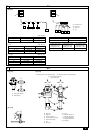
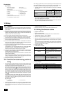
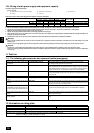
10.3
BA
C
~208–230 V
BA
~208–230 V
E E
D
E E
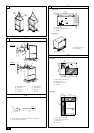
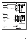
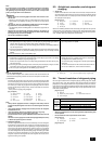
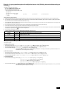
[Fig. 10.3.2]
[Fig. 10.3.1]
A: Group 1
B: Group 3
C: Group 5
D: Shielded wire
E: Sub remote
controller
( ) Address
<A> Change the jumper connec-
tor from CN41 to CN40
<B> SW2-1:ON
<C> Keep the jumper connector
on CN41
<B> SW2-1:ON
<A> Change the jumper connec-
tor from CN41 to CN40
<B> SW2-1:ON
<C> Keep the jumper connector
on CN41
<B> SW2-1:ON
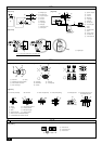
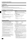
[Fig. 10.4.1]
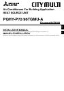
A: Switch (breakers for wiring and current leakage)
B: Breakers for current leakage
C: Heat source unit
D: Pull box
E: Indoor unit
10.4