


9
GB
D
FINL EPGRRUTR
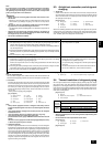
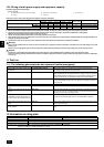
2 Water quality standard
Reference : Guideline of Water Quality for Refrigeration and Air Conditioning
Equipment. (JRA GL02E-1994)
3 Please consult with a water quality control specialist about water quality
control methods and water quality calculations before using anti-corrosive
solutions for water quality management.
4 When replacing a previously installed air conditioning device (even when
only the heat exchanger is being replaced), first conduct a water quality
analysis and check for possible corrosion.
Corrosion can occur in cold-water systems even if there has been no prior
signs of corrosion.
If the water quality level has dropped, please adjust water quality suffi-
ciently before replacing the unit.
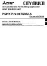
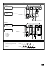
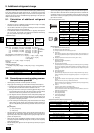
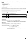
7.4. Pump interlock
The heat source unit may become damaged if it is operated with no water circulat-
ing through the pipes.
Be sure to interlock unit operation and the water-circuit pump. Use the terminal
blocks for interlocking (TB8-3, 4) that can be found on the unit.
In the case of a pump interlock circuit signal connection to the TB8-3, 4, remove
the short-circuit wire. Also, to prevent mistaken error detection, resulting from a
poor connection, in the pressure valve 63PW, use a low maintained current of 5mA
or less.
[Fig. 7.4.1] (P.2)
A Short-circuit wire (Connected before delivery from manufacturer)
B Pump interlock circuit connection
pH (25˚C) [77°F]
Electric conductivity
(mS/m) (25°C) [77°F]
(µ s/cm) (25°C) [77°F]
Chloride ion (mg Cl
-
/r)
Sulfate ion (mg SO4
2-
/r)
Acid consumption (pH4.8)
(mg CaCO
3
/r)
Total hardness (mg CaCO
3
/r)
Calcium hardness (mg CaCO
3
/r)
Ionic silica (mg SiO
2
/r)
Iron (mg Fe/r)
Copper (mg Cu/r)
Sulfide ion (mg S
2-
/r)
Ammonium ion (mg NH
4
+
/r)
Residual chlorine (mg Cl/r)
Free carbon dioxide (mg CO
2
/r)
Ryzner stability index
Standard
items
Refer-
ence
items
Items
Lower mid-range
temperature water system
7.0 ~ 8.0
30 or less
[300 or less]
50 or less
50 or less
50 or less
70 or less
50 or less
30 or less
1.0 or less
1.0 or less
not to be
detected
0.3 or less
0.25 or less
0.4 or less
–
7.0 ~ 8.0
30 or less
[300 or less]
50 or less
50 or less
50 or less
70 or less
50 or less
30 or less
0.3 or less
0.1 or less
not to be
detected
0.1 or less
0.3 or less
4.0 or less
–
Tendency
Recirculating
water
[20<T<60°C]
[68<T<140°F]
Make-up
water
Corrosive
Scale-
forming
8. Refrigerant piping installation
A Residues in commercially available antioxidants may have adverse effects on
the equipment. Braze only with non-oxide brazing material. The use of other
brazing material may result in compressor damage.
(Refer to item 9.2. for detailed information on pipe connections and valve op-
erations.)
B Never perform heat source unit piping connection work when it is raining.
Warning
When installing and moving the unit, do not charge it with refrigerant other
than the refrigerant specified on the unit.
- Mixing of a different refrigerant, air, etc. may cause the refrigerant cycle to mal-
function and result in severe damage.
Caution:
• Use a vacuum pump with a reverse flow check valve.
- If the vacuum pump does not have a reverse flow check valve, the vacuum
pump oil may flow back into the refrigerant cycle and cause deterioration of
the refrigerator oil and other trouble.
• Do not use the tools shown below used with conventional refrigerant.
(Gauge manifold, charge hose, gas leak detector, check valve, refrigerant
charge base, vacuum gauge, refrigerant recovery equipment)
- Mixing of conventional refrigerant and refrigerator oil may cause the refrig-
erator oil to deteriorate.
- Mixing of water will cause the refrigerator oil to deteriorate.
- R410A refrigerant does not contain any chlorine. Therefore, gas leak detec-
tors for conventional refrigerants will not react to it.
• Manage the tools more carefully than normal.
- If dust, dirt, or water gets in the refrigerant cycle, the refrigerator oil will dete-
riorate.
• Never use existing refrigerant piping.
- The large amount of chlorine in conventional refrigerant and refrigerator oil
in the existing piping will cause the new refrigerant to deteriorate.
• Store the piping to be used during installation indoors and keep both
ends of the piping sealed until just before brazing.
- If dust, dirt, or water gets into the refrigerant cycle, the oil will deteriorate and
the compressor may fail.
• Do not use a charging cylinder.
- Using a charging cylinder may cause the refrigerant to deteriorate.
• Do not use special detergents for washing piping.
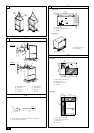
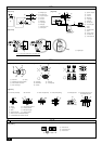
8.2. Refrigerant piping system
Connection Example
[Fig. 8.2.1] (P.3)
Å Heat source model ı Liquid pipe
Ç Gas pipe Î Total capacity of indoor units
‰ Model number Ï Downstream unit model total
Ì Branch kit model
Ó 4-Branching header (Downstream unit model total
<
=
200)
¬ 8-Branching header (Downstream unit model total
<
=
400)
Ô 10-Branching header (Downstream unit model total
<
=
650)
A Heat source unit B First branch
C Indoor unit D Cap
Connecting the piping is a terminal-branch type in which refrigerant piping from
the heat source unit is branched at the terminal and connected to each of the
indoor units.
The method of pipe connection is as follows: flare connection for the indoor units, gas
pipes for heat source units, flare connection for P72 and brazed connection for P96 ~
P168; liquid pipes, flare connection. Note that the branched sections are brazed.
Warning:
Always use extreme care to prevent the refrigerant gas from leaking while
using fire or flame. If the refrigerant gas comes in contact with a flame from
any source, such as a gas stove, it breaks down and generates a poisonous
gas which can cause gas poisoning. Never weld in an unventilated room.
Always conduct an inspection for gas leakage after installation of the refrig-
erant piping has been completed.
8.1. Caution
This unit uses refrigerant R410A. Follow the local regulations on materials and
pipe thickness when selecting pipes.
1 Use the following materials for refrigeration piping.
• Material: Use refrigerant piping made of phosphorus deoxidized copper.
In addition, be sure that the inner and outer surfaces of the pipes are clean
and free of hazardous sulphur, oxides, dust/dirt, shaving particles, oils,
moisture, or any other contaminant.
2 Commercially available piping often contains dust and other materials. Always
blow it clean with a dry inert gas.
3 Use care to prevent dust, water or other contaminants from entering the piping
during installation.
4 Reduce the number of bending portions as much as possible, and make bend-
ing radius as big as possible.
5 Always observe the restrictions on the refrigerant piping (such as rated length,
the difference between high/low pressures, and piping diameter). Failure to do
so can result in equipment failure or a decline in heating/cooling performance.
6 Either a lack or an excess of refrigerant causes the unit to make an emergency
stop. Charge the system with an appropriate amount of refrigerant. At such a
time, always properly charge the unit. When servicing, always check the notes
concerning pipe length and amount of additional refrigerant at both locations,
the refrigerant volume calculation table on the back of the service panel and
the additional refrigerant section on the labels for the combined number of
indoor units.
7 Use liquid refrigerant to fill the system.
8 Never use refrigerant to perform an air purge. Always evacuate using a vacuum
pump.
9 Always insulate the piping properly. Insufficient insulation will result in a de-
cline in heating/cooling performance, water drops from condensation and other
such problems.
0 When connecting the refrigerant piping, make sure the ball valve of the heat
source unit is completely closed (the factory setting) and do not operate it until
the refrigerant piping for the heat source and indoor units has been connected,
a refrigerant leakage test has been performed and the evacuation process has
been completed.