


MT-62HS — PARTS & OPERATION MANUAL — REV. #2 (12/15/03) — PAGE 13
MT-62HS — CONTROLS AND COMPONENTS
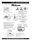
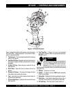
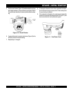
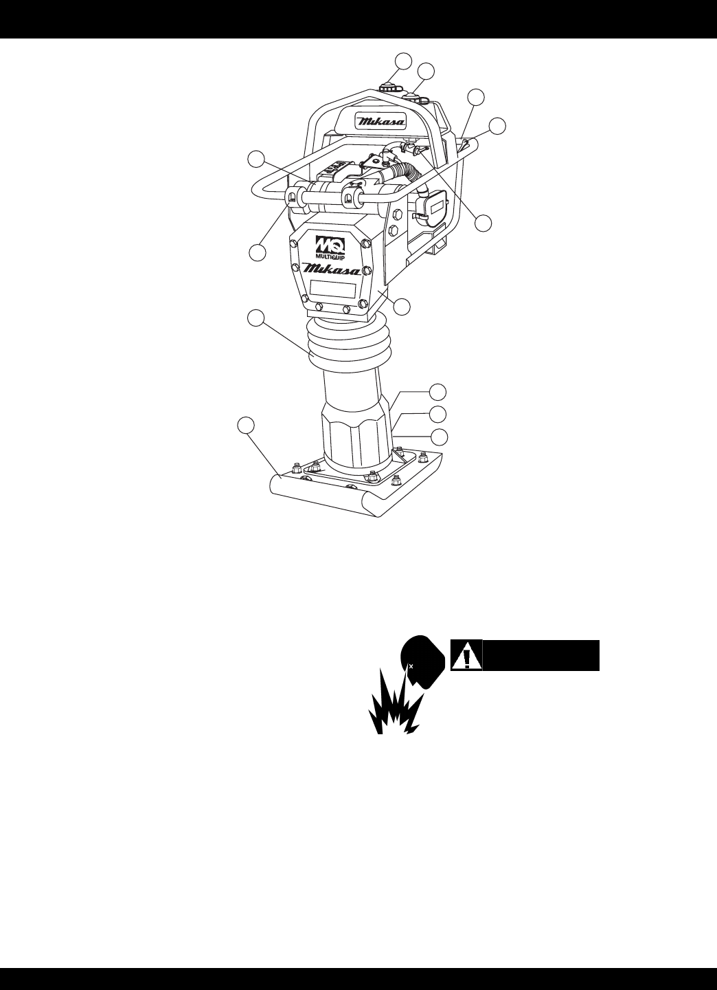
Figure 1 shows the location of the controls and components
for the MT-62HS Tamping Rammer. The functions of each
control is described below:
1. Throttle Lever – Controls engine speed and the tamping
action of the rammer.
2. Fuel Shut-Off Valve – Supplies fuel from the fuel tank to
the engine. To begin fuel flow move the fuel shut-off valve
downward.
3. Oil Bath Fill Plug – Open this plug to add oil to the oil
bath reservoir.
4. Drain Valve – Open this valve to remove oil from the
bellows.
5. Primary Air Cleaner – Pre-cleans (first stage) dirt and
other debris from entering the engine.
6. Foot– Laminated wood with tempered steel plate for
superior shock absorption.
7. Oil Level Sight Glass – Indicates the level of oil in the oil
bath reservoir.
Figure 1. MT-62HS Rammer
8. Fuel Tank/Cap – Remove this cap to add unleaded
gasoline to the fuel tank. Make sure cap is tightened securely.
DO NOT over fill.
Adding fuel to the tank should be accomplished only
when the engine is stopped and has had an
opportunity to
cool down.
In the event of a fuel spill,
DO NOT attempt to start the engine until the fuel
residue has been completely wiped up, and the area surrounding
the engine is dry.
9. Bellows – Reservoir for oil bath.
10. Handle – To operate rammer
GRIP
handle assembly
firmly on both sides.
11. Nameplate – Displays information regarding the rammer.
12. Roller Bar – Used when transporting rammer onto a
truck bed. Place rammer on this roller bar then slide.
13. Oil Tank/Cap – Fill oil tank with 2-stroke motor oil.
WARNING
MT-62HS
1
10
8
13
2
7
4
3
6
9
12
5
11