


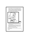

Installation
23
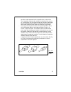
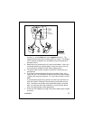
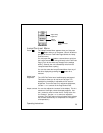
Fig. 2-17
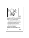
DC Power
Connections
terminal (+), and the
black
wire to the
negative
terminal (-). The
negative terminal may also be called “ground” or “earth.” (The display
unit is internally protected if you accidentally reverse the polarity of
the power wires.)
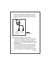
4. Attach the red or positive wire to a 5 amp circuit breaker. If the unit is
connected directly to the boat’s battery, include a 2 amp in-line fuse.
(In-line fuses are available at most marine supply stores.)
5. The power cable includes a smaller “shield” wire. Connect this to a
good ground.
6. If you need to extend the power wiring by more than 10 feet, use a
larger wire size. This will allow the wires to deliver the correct voltage
in spite of the longer wire distance. For runs of 20 to 35 feet, use #14
AWG.
If you extend the power wiring, be sure all electrical connections are
solid and durable. Soldering is the best way to make these connec-
tions. Insulate all connections using heat-shrink tubing or electrical
tape. You may also use crimp connectors or a terminal strip, but be
sure to use good-quality marine-grade parts.
7. At the rear of the display unit, plug in the power cable using the keyed
connector.
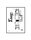
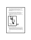
T/D
connector
to transducer
DC 12V
connector
to battery
BLACK
RF ground
RED
DC 12V