


16. If the first stage has a SAA-5300 DIN adapter installed instead of a standard yoke, see the
installation instructions given in Sherwood Technical Bulletin #104 for overhaul and installation
instructions of the DIN adapter.
4.4 TESTING OF FIRST STAGE
A. Before You Begin Testing
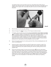
1. Install an intermediate pressure test gauge (p/n TL119) into one of the low pressure ports of the
first stage. Plug any open outlet ports with suitable port plugs.
2. Install the first stage onto a tank valve, and introduce 2700 - 3500 psig (186-240 bar) to the
inlet of the regulator. Flow air through the regulator by pushing the purge button on the second
stage several times to get all parts properly seated.
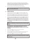
B. Dry Air Bleed Flow Test
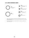
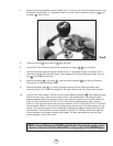
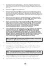
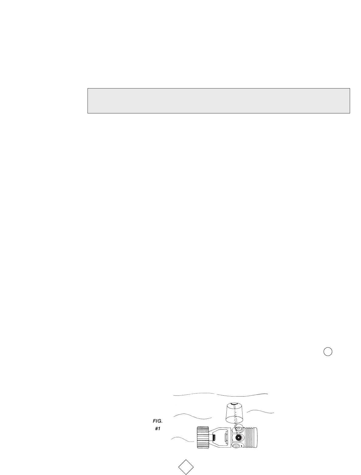
1. Submerge the first stage under several inches of water.
2. A small stream of bubbles should be escaping from the one-way bleed valve on the first stage
and nowhere else on the body (see Fig. 1). The number and size of the bubbles may vary from
regulator to regulator:
a. Invert a small (50 cc capacity) graduated cylinder (p/n TL110) filled with water over the
underwater flow of bubbles (see Fig. 1). The air entering the cylinder will gradually empty
some of the water out of the cylinder.
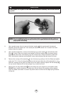
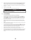
b. After one minute, remove the graduated cylinder from the air flow and raise the cylinder to
the surface so that the air/water dividing line inside the cylinder matches the water level
outside the cylinder. The measurement at this point should be between 13 and 27 cc for
the old style flow control elements and 20-30 cc for the new laser drilled flow control
elements.
c. If the reading is significantly higher than 30 cc, check the O-rings and sealing surfaces-
mated to the piston. If the reading is below 13 cc, check the flow control element to
determine if it has been clogged by grease or other foreign matter. If it is clogged, it must
be replaced (old style sintered stainless steel) or cleaned (new laser drilled element).
11
NOTE
: For safety, always test the first stage regulator with at least one second stage installed.The
demand valve on the second stage acts as a relief valve in the event of a malfunction.
18