


8. Tighten the screws using a # 10 Torx screw driver just enough to seat them snugly. There is no
reason to turn these screws beyond the first contact point.
Do not overtighten. This screw is
threading into plastic, which will hold well in service but is easily stripped if overtightened.
9. Install the mouthpiece . Be sure to position the mouthpiece so that the word “Sherwood” is
on the top.
10. Install a new mouthpiece tie .
11. Install one end of the hose into a serviced first stage, tighten snugly.
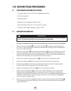
5.4 SET- UP OF SECOND STAGE
For the following adjustments, remove the cover and diaphragm.
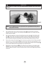
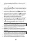
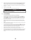
1. Install Sherwood’s in-line adjusting tool (p/n TL102) between the orifice housing and the
hose assembly . Use the tool to screw the adjustable orifice clockwise. Watch the end
of the lever as you do this. As soon as the tip of the lever begins to drop, stop turning the
tool. The slight amount of friction this operation produces between the orifice and the stem
seat will not harm the stem seat.
2. Attach the in-line tool and the second stage to its accompanying overhauled and properly
adjusted first stage, and mount on an air tank filled to between 2700 and 3500 psig (186 and
240 bar).
3.
Slowly turn on the tank valve. If you hear any leaks, determine the location of the leak, shut the
air off, and repair the leak as necessary.
4. Turn on the air. Use the in-line adjusting tool to turn the adjusting orifice counter-clockwise
until you hear a slight hissing. Then turn the adjusting orifice clockwise just enough to stop the
hissing. HINT: A slight clockwise turn past the point where the hissing just stops will reduce
wear and tear on regulators used heavily in rental or training situations.
5. Depress the lever assembly in the second stage five or six times to get the internal parts
seated in their proper positions. Listen for any hissing. Adjust if necessary.
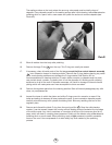
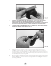
6. After setting the adjusting orifice, check the relationship between the diaphragm wear plate and
the tip of the lever assembly. To do this, use the Sherwood lever height gauge and adjusting
tool (p/n TL123). Use the tool as a gauge by laying it across the top of the case as shown in
Photo #4.
16
24
22
6
22
17
18
20
WARNING
NEVER tighten the hose with more than 40 in. lbs. (4.5 joules) of torque. The inlet hose
fitting can be weakened by overtightening.