


5-14
AS1021M-T2/1021M-82 User's Manual
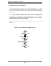
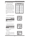
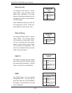
Overheat/Fan Fail LED
Connect an LED to the OH connection
on pins 7 and 8 of JF1 to provide ad-
vanced warning of chassis overheat-
ing. Refer to the table on the right for
pin defi nitions and status indicators.
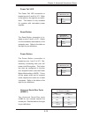
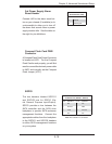
NIC1 LED
The NIC1 (Network Interface Control-
ler) LED connection is located on pins
11 and 12 of JF1. Attach the NIC1
LED cable to display network activity.
Refer to the table on the right for pin
defi nitions.
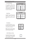
NIC2 LED
The NIC2 (Network Interface Control-
ler) LED connection is located on pins
9 and 10 of JF1. Attach the NIC2
LED cable to display network activity.
Refer to the table on the right for pin
defi nitions.
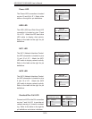
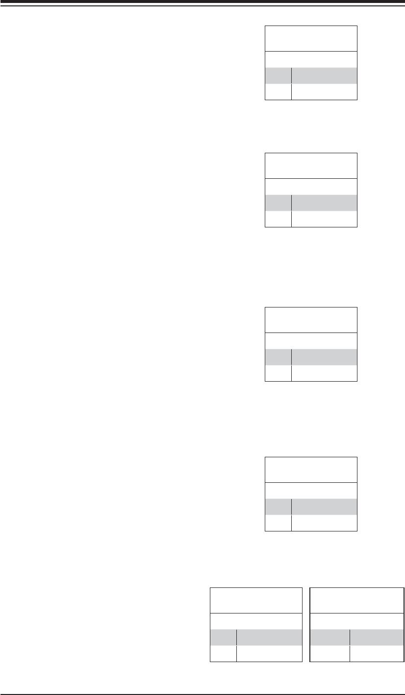
OH/Fan Fail LED
Pin Defi nitions (JF1)
Pin# Defi nition
7 Vcc
8 Control
NIC1 LED
Pin Defi nitions (JF1)
Pin# Defi nition
11 Vcc
12 NIC1 Active
NIC2 LED
Pin Defi nitions (JF1)
Pin# Defi nition
9 Vcc
10 NIC2 Active
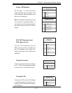
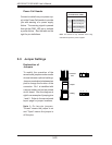
HDD LED
The HDD (IDE Hard Disk Drive) LED
connection is located on pins 13 and
14 of JF1. Attach the IDE hard drive
LED cable to display disk activity.
Refer to the table on the right for pin
defi nitions.
HDD LED
Pin Defi nitions (JF1)
Pin# Defi nition
13 Vcc
14 HD Active
OH/Fan Fail
LED Status
State Indication
Solid Overheat
Blinking Fan fail
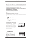
Power LED
The Power LED connection is located
on pins 15 and 16 of JF1. Refer to the
table on the right for pin defi nitions.
Power LED
Pin Defi nitions (JF1)
Pin# Defi nition
15 Vcc
16 Control