


5-20
AS1021M-T2/1021M-82 User's Manual
5-9 Jumper Settings
Explanation of
Jumpers
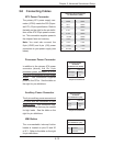
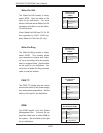
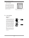
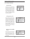
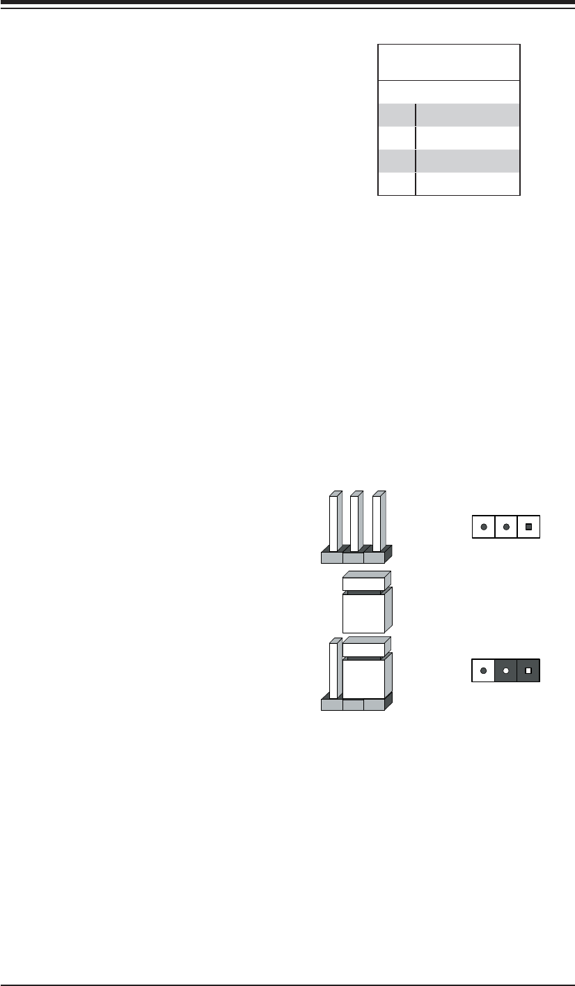
To modify the operation of the
serverboard, jumpers can be used to
choose between optional settings.
Jumpers create shorts between two
pins to change the function of the
connector. Pin 1 is identifi ed with
a square solder pad on the printed
circuit board. See the diagram at
right for an example of jumping pins
1 and 2. Refer to the serverboard
layout page for jumper locations.
Note 1: On two-pin jumpers,
"Closed" means the jumper is on
and "Open" means the jumper is
off the pins.
Connector
Pins
Jumper
Setting
321
321
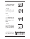
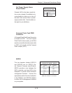
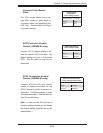
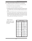
Power Fail Header
Connect a cable from your power sup-
ply to the Power Fail header to provide
you with warning of a power supply
failure. The warning signal is passed
through the PWR_LED pin to indicate
a power failure. See the table on the
right for pin defi nitions.
Power Fail Header
Pin Defi nitions (JPWF)
Pin# Defi nition
1 P/S 1 Fail Signal
2 P/S 2 Fail Signal
3 P/S 3 Fail Signal
4 Alarm Reset
Note: This feature is only available when using
redundant Supermicro power supplies.