


6-8
AS1021M-T2/1021M-82 User's Manual
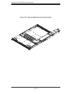
DVD-ROM and Floppy Drive Installation
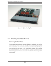
The top cover of the chassis must be opened to gain full access to the DVD-ROM
and fl oppy drive bays. The AS1021M-T2/1021M-82 accomodates only slim-line
DVD-ROM drives. Side mounting brackets are needed to mount a slim-line DVD-
ROM drive in the AS1021M-T2/1021M-82 server.
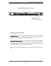
You must power down the system before installing or removing a fl oppy or DVD-
ROM drive. First, release the retention screws that secure the server unit to the
rack. Grasp the two handles on either side and pull the unit straight out until it locks
(you will hear a "click"). Next, depress the two buttons on the top of the chassis
to release the top cover and at the same time, push the cover away from you until
it stops. You can then lift the top cover from the chassis to gain full access to the
inside of the server.
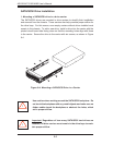
With the chassis cover removed, unplug the power and data cables from the drive
you want to remove. Then locate the locking tab at the rear of the drive. It will be
on the left side of the drive when viewed from the front of the chassis. Pull the tab
away from the drive and push the drive unit out the front of the chassis. Add a new
drive by following this procedure in reverse order. You may hear a faint *click* of the
locking tab when the drive is fully inserted. Remember to reconnect the data and
power cables to the drive before replacing the chassis cover and restoring power
to the system. Please be aware of the following:
• The fl oppy disk drive cable has seven twisted wires.
• A color mark on a cable typically designates the location of pin 1.
• A single fl oppy disk drive ribbon cable has 34 wires and two connectors to provide
for two fl oppy disk drives. The connector with twisted wires always connects to
drive A, and the connector that does not have twisted wires always connects to
drive B.