


Chapter 5: Advanced Serverboard Setup
5-25
5-11 Floppy, IDE, SATA and SCSI Drive Connections
Use the following information to connect the fl oppy and hard disk drive cables.
The fl oppy disk drive cable has seven twisted wires.
A red mark on a wire typically designates the location of pin 1.
A single fl oppy disk drive ribbon cable has 34 wires and two connectors to provide
for two fl oppy disk drives. The connector with twisted wires always connects to
drive A, and the connector that does not have twisted wires always connects to
drive B.
The 80-wire ATA133 IDE hard disk drive cable that came with your system has
two connectors to support two drives. This special cable should be used to take
advantage of the speed this new technology offers. The blue connector connects
to the onboard IDE connector interface and the other connector(s) to your hard
drive(s). Consult the documentation that came with your disk drive for details
on actual jumper locations and settings for the hard disk drive.
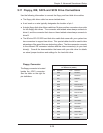
Floppy Drive Connector
Pin Defi nitions (JFDD1)
Pin# Defi nition Pin # Defi nition
1 GND 2 FDHDIN
3 GND 4 Reserved
5 Key 6 FDEDIN
7 GND 8 Index-
9 GND 10 Motor Enable
11 GND 12 Drive Select B-
13 GND 14 Drive Select A-
15 GND 16 Motor Enable
17 GND 18 DIR-
19 GND 20 STEP-
21 GND 22 Write Data-
23 GND 24 Write Gate-
25 GND 26 Track 00-
27 GND 28 Write Protect-
29 GND 30 Read Data-
31 GND 32 Side 1 Select-
33 GND 34 Diskette
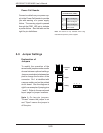
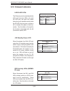
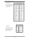
Floppy Connector
The fl oppy connector is located
beside the JIDE1 connector.
See the table on the right for
pin defi nitions.