


Relay PCA 04523 Addendum to E-Series Operator Manuals
2. OPERATION AND CONFIGURATION
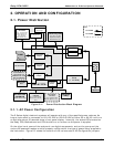
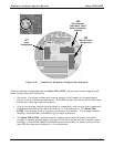
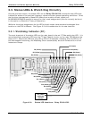
2.1. Power Distribution
SENSOR SUITES
LOGIC DEVICES
(e.g. CPU, I
2
C bus,
Keyboard, Display,
MotherBoard, etc.)
RELAY PCA
ON / OFF
SWITCH
PS 2
(+12 VDC)
OPTIONAL
VALVES
(e.g. Sample/Cal,
Zero/Spans, etc.)
MODEL SPECIFIC
VALVES
(e.g. M/R Valves,
Auto-zero valves,
etc.)
COOLING
FAN(S)
UV SHUTTER
SOLENOID
(M100E Series Only)
PUMP
AC HEATERS
AC HEATERS for
OPTIONAL IZS
PERMEATION TUBE
AND O2 SENSOR
PS 1
ANALOG
SENSORS
(e.g. UV sensors,
Temp Sensors,
Flow Sensors,
IR, Sensors,
PMT HVPS, etc.)
Pre-Amplifiers
& Amplifiers
Sensor Control
& I/O Logic
Solenoid
Drivers
KEY
AC POWER
DC POWER
AC
POWER IN
+5 VDC
±15 VDC
Configuration
Jumpers
Configuration
Jumpers
Configuration
Jumpers
UV Lamp
P/S
Figure 2-1: Power Distribution Block Diagram
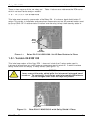
2.1.1. AC Power Configuration
The E-Series digital electronic systems will operate with any of the specified power regimes. As
long as instrument is connected to 100-120 VAC or 220-240 VAC at either 50 or 60 Hz it will turn
on and after about 30 seconds show a front panel display. Internally, the status LEDs located on
the Relay PCA, Motherboard and CPU should turn on as soon as the power is supplied.
On the other hand, some of the analyzer’s non-digital components, such as the pump and the
various AC powered heaters must be properly configured for the type of power being supplied to
the instrument. Figure 2-3 shows the location of the various sets of AC Configuration jumpers.
05118 Rev B3 5