


Relay PCA 04523 Addendum to E-Series Operator Manuals
TABLE OF CONTENTS
1. INTRODUCTION ........................................................................................................................... 1
1.1. What’s the Same.....................................................................................................................1
1.2. What’s Different ......................................................................................................................2
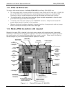
1.3. Relay PCA Location and Layout..................................................................................................2
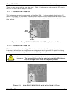
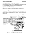
1.3.1. Version 045230200 ...........................................................................................................3
1.3.2. Version 045230100 ...........................................................................................................3
2. OPERATION AND CONFIGURATION.............................................................................................. 5
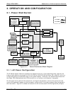
2.1. Power Distribution ...................................................................................................................5
2.1.1. AC Power Configuration .....................................................................................................5
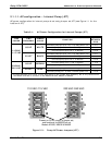
2.1.1.1. AC configuration – Internal Pump (JP7)..........................................................................7
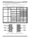
2.1.1.2. AC Configuration – Standard Heaters (JP2).....................................................................8
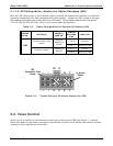
2.1.1.3. AC Configuration –Heaters for Option Packages (JP6).......................................................9
2.2. Valve Control..........................................................................................................................9
2.3. Status LEDs & Watch Dog Circuitry ..........................................................................................10
2.3.1. Watchdog Indicator (D1)..................................................................................................10
2.4. Heater Control Loop...............................................................................................................11
2.4.1. Thermocouple Inputs and Configuration Jumper (JP5) ..........................................................12
2.5. DC Power Supply Test Points...................................................................................................14
3. TROUBLE SHOOTING AND REPAIR ..............................................................................................15
3.1. Removing / Replacing the Relay PCA from the Instrument...........................................................15
4. SCHEMATICS AND SPARE PARTS FOR RELAY PCA P/N 04523.....................................................16
LIST OF FIGURES
Figure 1-1: Relay PCA Layout (P/N04523)..........................................................................2
Figure 1-2: Relay PCA P/N 045230200 with AC Relay Retainer In Place..................................3
Figure 1-3: Relay PCA P/N 045230100 with Safety Shield In Place.........................................3
Figure 2-1: Power Distribution Block Diagram.....................................................................5
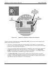
Figure 2-2: Location of AC power Configuration Jumpers......................................................6
Figure 2-3: Pump AC Power Jumpers (JP7) ........................................................................7
Figure 2-4: Typical Set Up of AC Heater Jumper Set (JP2)....................................................8
Figure 2-5: Typical Set Up of AC Heater Jumper Set (JP2)....................................................9
Figure 2-6: Status LED Locations – Relay PCA 04523......................................................... 10
Figure 2-7: Heater Control Loop Block Diagram. ............................................................... 11
Figure 2-8: Thermocouple Configuration Jumper (JP5) Pin-Outs.......................................... 13
Figure 3-1: Relay PCA 04523 Mounting Screw Locations .................................................... 15
LIST OF TABLES
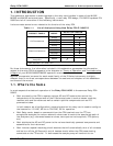
Table 1-1: List of Analyzers Using New Relay PCA P/N04523 ................................................ 1
Table 2-1: AC Power Configuration for Internal Pumps (JP7).................................................7
Table 2-2: Power Configuration for Standard AC Heaters (JP2) .............................................8
Table 2-3: Power Configuration for Optional AC Heaters (JP6)...............................................9
Table 2-4: Thermocouple Configuration Jumper (JP5) Pin-Outs ........................................... 12
Table 2-5: Typical Thermocouple Settings for M100E/M200E series analyzers ....................... 13
Table 2-5: DC Power Test Point and Wiring Color Code ...................................................... 14
Table 2-6: DC Power Supply Acceptable Levels................................................................. 14
Table 4-1: List of Spare Parts......................................................................................... 16
Table 4-2: List of Included Electronic Schematics.............................................................. 16
05118 Rev B3 i