


Addendum to E-Series Operator Manuals Relay PCA 04523
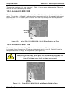
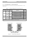
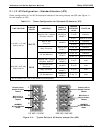
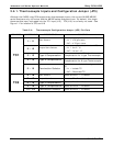
2.1.1.2. AC Configuration – Standard Heaters (JP2)
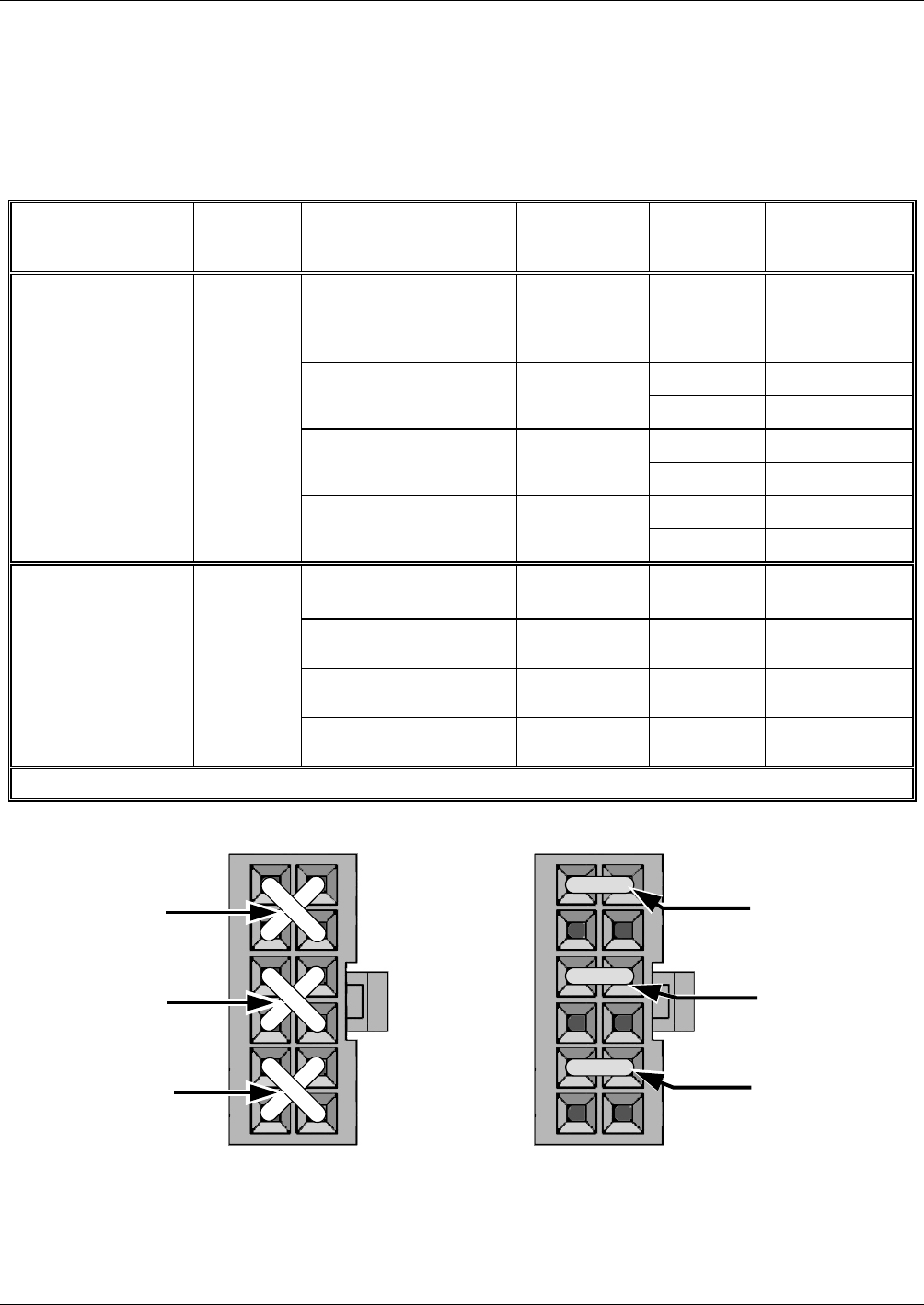
Power configuration for the AC the standard heaters is set using Jumper set JP2 (see Figure 1-1
for the location of JP2).
Table 2-2: Power Configuration for Standard AC Heaters (JP2)
LINE VOLTAGE
JUMPER
COLOR
HEATER(S)
MODEL’S
USED ON
1
JUMPER
BETWEEN
PINS
FUNCTION
1 to 8
Common
Reaction Cell / Sample
Chamber Heaters
M100E’s &
M200E’s
2 to 7
Neutral to Load
3 to 10
Common
Mini Hi-Con
Converter
M200EH
4 to 9
Neutral to Load
3 to 10
Common
Moly Converter
M101E and
M200E’s
4 to 9
Neutral to Load
5 to 12
Common
110 VAC / 115 VAC
50Hz & 60 Hz
WHITE
By Pas Manifold
M200#M &
M200EH
6 to 11
Neutral to Load
Reaction Cell / Sample
Chamber Heaters
2
M100E’s &
M200E’s
1 to 7
Load
Hi Concentration
Converter
M100EH
3 to 9
Load
Moly Converter
M101E and
M200E’s
3 to 9
Load
220 VAC / 240 VAC
50Hz & 60 Hz
BLUE
By Pas Manifold
M200#M &
M200EH
5 to 11
Load
1
No AC Heaters are used in the M400E series analyzers.
1
2
3
4
5
6
7
8
9
10
11
12
Reaction Cell or
Sample Chamber
Heaters
Mini Hi-Con or
Moly Converter
Heaters
200EM/EH
By Pass Manifold
Heater
110 VAC /115 VAC
1
2
3
4
5
6
7
8
9
10
11
12
Reaction Cell or
Sample Chamber
Heaters
Mini Hi-Con or
Moly Converter
Heaters
200EM/EH
By Pass Manifold
Heater
220 VAC / 240 VAC
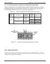
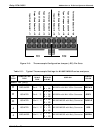
Figure 2-4: Typical Set Up of AC Heater Jumper Set (JP2)
8 05118 Rev B3