


Addendum to E-Series Operator Manuals Relay PCA 04523
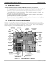
2.3. Status LEDs & Watch Dog Circuitry
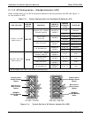
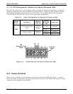
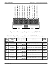
Like the previous version, the status LED’s on the Relay PCA 04523 includes thirteen LEDs that
indicate the status of the analyzer’s heaters, valves and other general operating conditions. Since
the functions represented by these LED differs from model to model, check your
M100E/M200E/M400E operator’s manual for their exact assignments (this can normally be found
in the section on Electronic Theory of Operation).
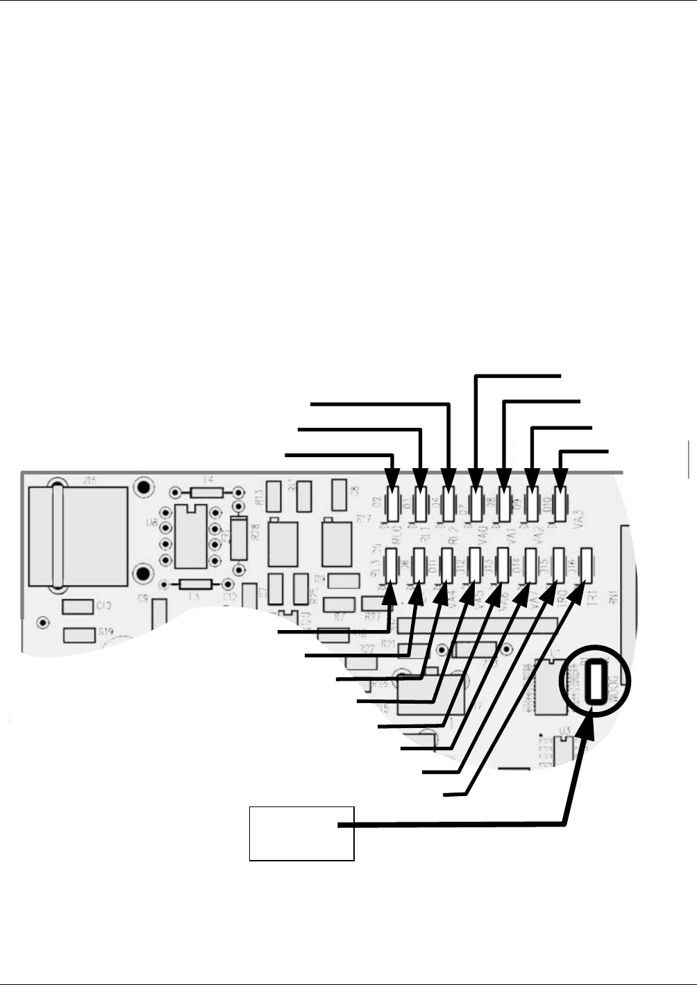
While the functional assignments for the LED’s of each model have remained unchanged their
location on the PCA is different. See Figure 2-3 of this addendum for the new locations.
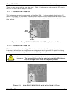
2.3.1. Watchdog Indicator (D1)
The most important of the status LED’s on the relay board is the red I
1
C Bus watch-dog LED. It is
controlled directly analyzer’s CPU over the I
2
C bus. Special circuitry on the relay PCA watches the
status of D1. Should this LED ever stay ON or OFF for 30 seconds, indicating that the CPU or I
2
C
bus has stopped functioning, this Watchdog Circuit automatically shuts all valves and turn off all
heaters and lamps.
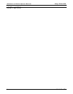
D3 (Yellow)
D4 (Yellow)
D2 (Yellow)
D5(Yellow)
D6 (Yellow)
D7 (Green)
D8 (Green)
D9 (Green)
D10 (Green)
D11 (Green)
D12 (Green)
D13 (Green)
D14 (Green)
D15 (Green)
D16 (Green)
D1 (RED)
Watchdog
Indicator
Figure 2-6: Status LED Locations – Relay PCA 04523
10 05118 Rev B3