


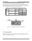
Addendum to E-Series Operator Manuals Relay PCA 04523
1.2. What’s Different
The major differences between the Relay PCA 04523 and Relay PCA 03955 are:
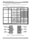
On instruments with internal pumps, the pump is now configured for use with 110 VAC, 60
Hz vs. 220 VAC, 50 Hz operation by a set of configuration jumpers on the Relay PCA.
Previously a set of inline connectors and wiring harnesses performed this function.
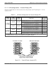
The configurability of the two thermocouple inputs has been expanded to allow for both
grounded and ungrounded thermocouples
A retainer plate has been added to the 045230200 version to keep the solid state AC
power relays securely inserted in their sockets.
Because the board has been physically changes, locations of components such as jumper
blocks, connectors and status LED’s have changed.
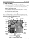
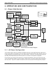
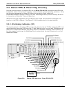
1.3. Relay PCA Location and Layout
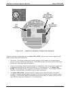
Generally the relay PCA is located in the right-rear quadrant of the analyzer and is mounted
vertically on the back side of the same bracket as the instrument’s DC power supplies, however
the exact location of the relay PCA may differ from model to model. Please check the Getting
Started chapter of your M100E/M200E/M400E operator’s manual.
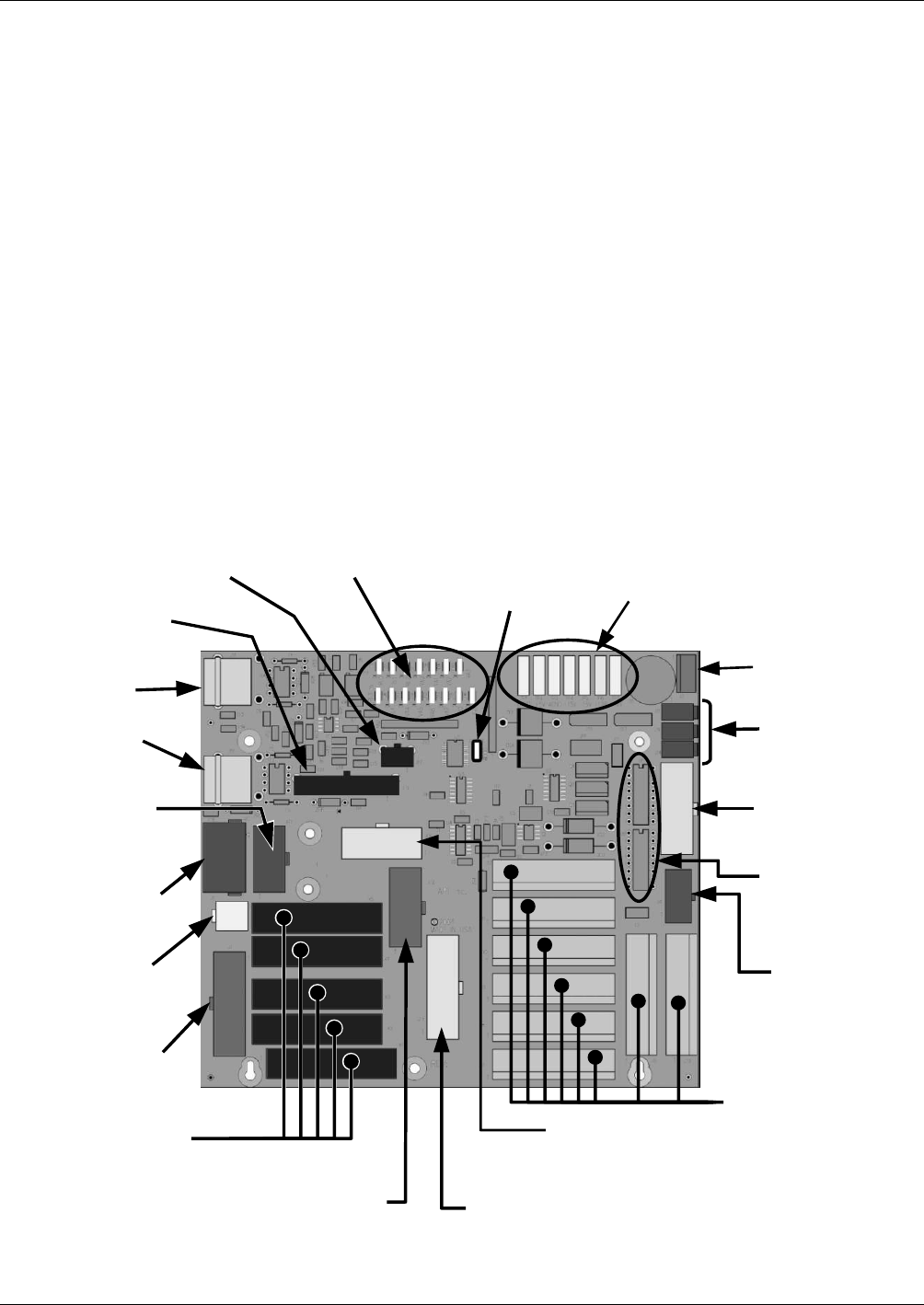
Power
Connection
for DC
Heaters
Status LED’s
(D2 through D16)
DC Power Supply
Test Points
Watchdog
Status LED
(D1)
(JP5)
Thermocouple
Configuration
Jumpers
Thermocouple
Signal Output
I
2
C
Connector
Shutter Control
Connector
(M100E Series
Only)
V
alve Control
Drivers
Pump Power
Output
(JP7)
Pump AC
Configuration
Jumper
AC Power
IN
AC Heater
Power Output
A
C Power Output for
Optional IZS Valve
Heaters & 0
2
sensors
(JP6)
Main AC Heater
Configuration Jumpers
(JP2)
AC Configuration Jumpers
for Optional IZS Valve
Heaters & 0
2
Sensors
Solid State AC
Power Relays
(Not Present on
P/N 45230100)
DC Power
Distribution
Connectors
V
alve Option
Control
Connector
(J15)
TC1 Input
(J16)
TC2 Input
Figure 1-1: Relay PCA Layout (P/N04523)
2 05118 Rev B3