


Addendum to E-Series Operator Manuals Relay PCA 04523
2.5. DC Power Supply Test Points
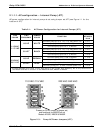
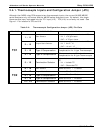
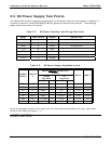
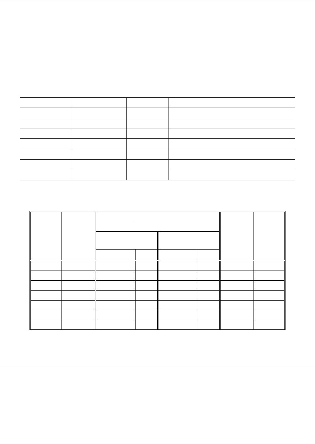
The tables defining the names and functions of the DC power test point that appear in Chapter 11
of some revisions of the M100E/M200E/M400E operator’s manual are incorrect. The following
tables show the correct information.
Table 2-5: DC Power Test Point and Wiring Color Code
NAME TEST POINT# COLOR DEFINITION
DGND
1
Black Digital ground
+5V
2
Red
AGND
3
Green Analog ground
+15V
4
Blue
-15V
5
Yellow
+12R
6
Purple 12 V return (ground) line
+12V
7
Orange
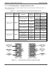
Table 2-6: DC Power Supply Acceptable Levels
CHECK RELAY BOARD TEST
POINTS
FROM
Test Point
TO
Test Point
POWER
SUPPLY
VOLTAG
E
NAME # NAME #
MIN V MAX V
PS1 +5 DGND 1 +5 2 +4.80 +5.25
PS1 +15 AGND 3 +15 4 +13.5 +16.0
PS1 -15 AGND 3 -15V 5 -14.0 -16.0
PS1 AGND AGND 3 DGND 1 -0.05 +0.05
PS1 Chassis DGND 1 Chassis N/A -0.05 +0.05
PS2 +12 +12V Ret 6 +12V 7 +11.8 +12.5
PS2 DGND +12V Ret 6 DGND 1 -0.05 +0.05
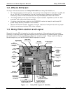
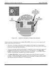
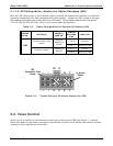
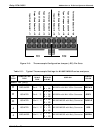
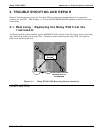
As on the previous version of the relay card, the test points are located at the top, right-hand
corner of the PCA (see Figure 1-1)
USER NOTES:
14 05118 Rev B3