


English 3
1. Introduction
Thank you for your purchase of this Prosine Sine
Wave Inverter. As a high quality, true sine wave output
inverter, you can expect exceptional performance and
years of dependable operation. The true sine wave AC
output from the inverter ensures all AC loads operating
from the unit perform efficiently and correctly. Since
these loads were designed to operate from true sine wave
voltage, you can expect these loads to operate the same
as if operating from grid/utility supplied power. In some
cases, the true sine wave output from the Xantrex inverter
is even superior to the power supplied by your utility
company.
To get the most out of your Prosine Inverter, carefully
read and follow the instructions in this guide. Pay special
attention to the Important Safety Instructions and to the
CAUTION and WARNING statements found
throughout the manual and on the product. Please retain
all packaging.
Should you have any questions before, during, or after
installation, please contact Xantrex.
Phone: 1-800-670-0707, 1-408-987-6030 (direct)
Fax: 1-800-994-7828, 1-604-422-2756 (direct)
Email: customerservice@xantrex.com
Web: www.xantrex.com
1.1 Prosine Inverter Key Features
The Prosine Inverter utilizes advanced high frequency
switching technology in the power conversion process.
The circuits are similar to those used in power supplies
for computers and other electronic equipment. This
technology offers several benefits:
• Light weight: for easy installation
• Totally silent: for quiet operation
• High surge capability: for “hard-to-start” AC loads
See Section 10 (Specifications) for complete product
specifications.
1.1.1 Inverter Function
When connected properly and the power switch is turned
to the (I) position, the inverter draws power from a battery
and delivers a true sine wave AC output voltage. If the
battery voltage is within the operating range of the unit,
the inverter will continue to deliver AC power to the
loads connected. High and low battery shutdowns will
engage if the battery voltage falls out of the specified
range of operation (10–16 VDC on 12 V models, 20–32
VDC on 24 V models).
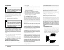
1.1.2 Control Panel
The Control Panel displays operating information so you
can monitor the status of the Inverter and your batteries.
This panel can be removed and re-attached in different
orientations so the information is directed at you in the
most convenient fashion, for all recommended mounting
configurations. With the optional Interface Panel, the
display can be fully removed from the base chassis and
remotely located in the place of your choice (e.g. on the
dash of your vehicle).
1.1.3 Automatic Transfer Switch
Your Prosine Inverter may be equipped with a transfer
relay if specified prior to purchase. The transfer relay serves
two purposes: 1) allows the AC output of the inverter to
be wired into an existing AC system as a source of power
and 2) allows the Prosine Inverter to automatically
become the source of power should your utility source
fail.
When utility AC power fails, the transfer relay is de-
energized and the load is automatically transferred to the
inverter output within 20–30 milliseconds. With the
POWERSAVE feature enabled (recommended for
reducing standby power consumption), AC output from
the inverter may be delayed for up to 2½ seconds. Once
AC utility is restored, the relay energizes and the load is
automatically reconnected to AC utility.
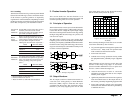
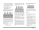
Identifying Models With Transfer Switches
1) Check the UPC code on the product box. Units with
transfer switches have UPC codes that end with these five
digits:
2) If there is an AC outlet on the front of the unit, it is
not equipped with an internal transfer switch.
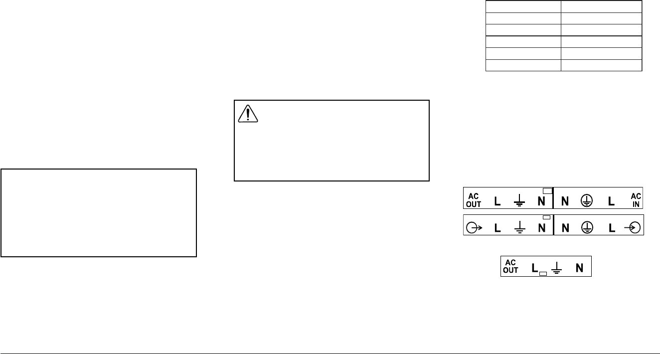
3) For Prosine Inverters with hardwire connections, you
can identify whether your unit has an internal transfer
switch by removing the cover on the AC wiring
compartment and checking the label above the terminal
block inside.
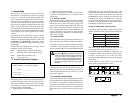
If your unit has a label similar to one of these two
labels, it has an internal transfer switch:
Units with this label do not have an internal transfer
switch:
i0001/0001ledoMi0081/0081ledoM
4801648816
4701647816
2501625816
8001680816
2001620816
WARNING
Note that in (
##
##
#) (Bypass) position the front panel
switch does NOT turn off all voltages inside the
unit. This control only deactivates the AC
conversion circuitry. On AC hardwire/transfer re-
lay versions any utility voltage present on the AC
input terminals will be present on the AC output
terminals.
Please record the following information if you need
to contact Xantrex for servicing of the unit.
Serial No.: ___________________________
Place of purchase: ___________________________
Date of purchase: ___________________________
Xantrex Prosine Inverter Owner’s Manual