


English 5
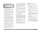
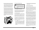
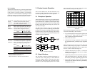
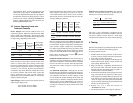
2. Remove and re-attach the front panel depending on
the orientation of the base unit itself. For example, if
the unit is mounted on a vertical surface, you may
want to remove the panel and attach it so it is again
readable horizontally. This can be done by removing
the four screws, taking the panel out of the housing,
rotating the panel and reattaching the panel to the
base unit. Be sure to re-install all four screws.
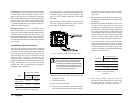
3. The front panel can also be remotely located away
from the base chassis. Simply remove the panel
from the face of the unit, install the interface panel
option (purchased separately) and connect the 30
ft. (9 m) extension cord. The cord can then be run to
the location where the panel is to be mounted, and
attached to the panel. The unit can now be controlled
and monitored from the location of your choice. Do
not remotely mount the display panel without
purchasing the Interface Panel option and properly
installing this panel on the inverter. The Interface
Panel significantly reduces radiated interference
generated along the length of the cable, decreasing
the chance of resulting interference with other
equipment.
2.4 Wiring the Prosine Inverter
For units equipped with an AC outlet:
If your Prosine Inverter is equipped with an AC outlet
on the front, then you will be mainly interested in the
DC wiring instructions that follow (section 2.4.4). Once
your DC connections and ground wiring connection are
complete, the unit is ready to deliver AC power.
For AC hardwire versions:
If your unit is equipped with an AC hardwire terminal
strip, (with or without transfer relay) then the following
AC wiring instructions are important for you to read
through. When hardwire configured, the inverter
manages all AC power and therefore must be wired in
between any utility connection and distribution panel.
As a starting point for the wiring instructions, here is a
brief summary of the wiring sequence for hardwire
configured inverters. Please thoroughly read the
remainder of the wiring instructions (section 2.4.2)
which details each wiring step and follows the Input
and Output Protection section:
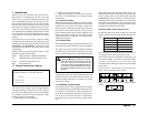
1. Ensure the (
##
##
#/I) control panel switch is in the (
##
##
#)
position. For those hardwire equipped models with
a transfer relay, connected AC source (INPUT)
power will be passed through the inverter making
the output terminal and connected wiring live. This
is the case even with the control panel switch in
the (
##
##
#) position so ensure all power is disconnected
at its source.
2. Connect AC input wiring, AC output wiring, Chassis
Ground, DC positive cable and finally, DC negative
cable in that order.
3. Connect each circuit to its source.
2.4.1 Input and Output Protection
In order to meet CSA, UL, and electrical code
requirements, the AC and DC inputs and outputs of the
Prosine Inverter must be provided with overcurrent
protection such as a circuit breaker or fuse, and with a
disconnect device, as follows: (note the “AC Input” and
“AC Output” information below only applies to units
equipped with AC hardwire terminal strips, not AC
output receptacle equipped versions).
DC Input: Protection for the DC wiring (an inline fuse
/circuit breaker) is needed as close as possible to the
battery to protect the wiring from your batteries to the
Prosine Inverter. The current rating of this DC fuse or
circuit breaker must be large enough to allow the inverter
to operate your loads, but if the rating is too high,
electrical codes will require you to use larger DC cables
than you would otherwise have to. The fuse or circuit
breaker must be rated and approved for use on minimum
12V or 24V DC circuits as applicable by the model of
your inverter. Fuses or circuit breakers rated only for
AC service are not suitable for use on DC circuits and
may pose a hazard. The wire size used between the
Prosine Inverter and the fuse or circuit breaker must be
sized to match the fuse or circuit breaker´s current rating,
in accordance with the electrical codes or regulations
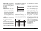
applicable to your installation (see Table 4).
AC Input: The installation must provide over-current
protection for the AC input circuit. The circuit breaker
or fuse used must be rated and approved for use on
120VAC branch circuits for 120V models and for
230VAC branch circuits for 230V models. The wire
size used between the breaker and the Prosine Inverter
input must be sized to match the circuit breaker, in
accordance with the electrical codes or regulations
applicable to your installation. Refer to Table 1 for
sizing information.
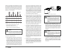
WARNING
Fire and shock hazard. Make sure wiring is
disconnected from all electrical sources
before handling. All wiring must be done in
accordance with local and national electrical
wiring regulations by a certified electrician or
technician.
Figure 2. Control panel attachment
Xantrex Prosine Inverter Owner’s Manual