


13
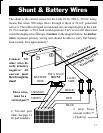
Shunt & Battery Wires
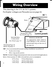
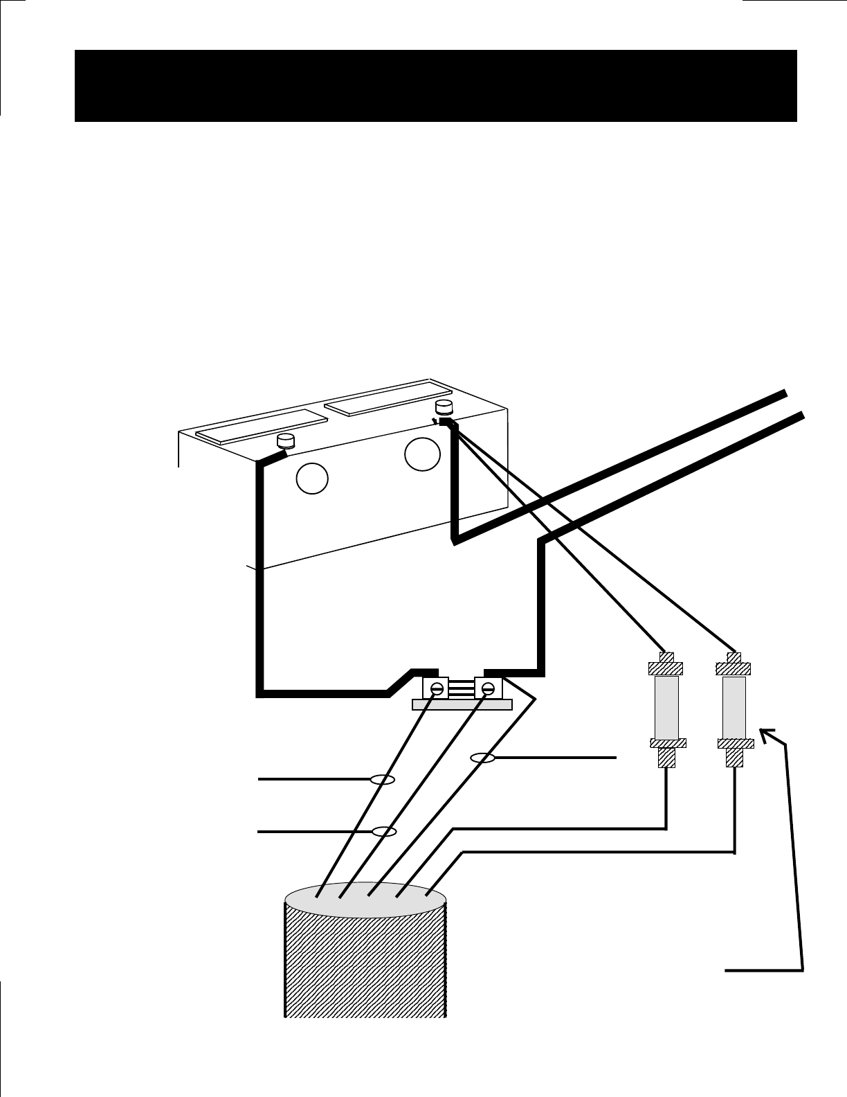
The shunt is the current sensor for the Link 10. Its 500 A, 50 mV rating
means that when 500 amps flows through it there is 50 mV generated
across it. The millivolt signal is translated into an amps display in the Link
10. For example: a 50 A load would generate 5 mV across the shunt and
would be displayed as
50 amps. Caution: in the diagram below, the darker
wires represent primary wiring and should be able to carry full battery
load current. Size appropriately!
RED
BLUE
+
-
ORANGE
GREEN
These wires
must be a
twisted pair!!
4 Twisted pair
cable. See page 14
for part numbers.
2 amp Fuses
(mount within 7"
of battery)
BLACK
SYSTEM POSITIVE
Connect NO
other wires di-
rectly to battery
negative! All
current must
flow through the
shunt!
BATTERY
SIDE
LOAD
SIDE
500 A 50 mV
SHUNT
SYSTEM NEGATIVE
LOAD SIDE