


15
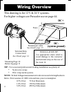
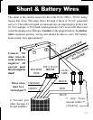
Most failures and problems are due to wiring errors. Please double check
the wiring. (Color code shown is for Xantrex wire P/Ns on page 14.)
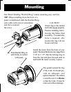
#1 - DC Power (Black Wire). Start at terminal #1 of the Link 10 and
follow it to the big bolt on the Load side of the shunt. Do not connect this
wire to the small screw terminal with the Green shunt sense lead.
#2 Shunt Sense Lead Load Side (Green Wire). This wire connects to
the small screw on the Load side of the shunt.
This wire must be a
twisted pair with the Orange wire described below. To check this wire
start at terminal #2 and follow it to the small screw on the Load side of
the shunt. There should be no other wires connected to this screw.
NOTE: Also check the primary wiring from the shunt to the battery.
There should be only one heavy cable from the Battery side of the shunt to
the battery. All loads and sources must be connected on the other side of
the shunt. Only the shunt may be connected directly to battery negative!
#3 Battery Side of Shunt (Orange Wire). This wire must be a twisted
pair with the Green wire described above. To check this wire start at
terminal #3 and follow it to the small screw on the Battery side of the
shunt. There should be no other wires connected to this screw.
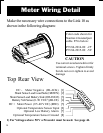
#4 Voltage Sense Wire (Bat.+) (Blue Wire). From terminal #4 this wire
should run to a 2 amp fuse holder, located within 7" of the battery. The
other side of the fuse holder should go to the positive (+) battery post.
If Voltage is greater than 50 V, see High Voltage Prescaler, page 44.
#5 + DC Power (Red Wire). This wire should run from terminal #5 to a
2 amp fuse holder located within 7" of the battery. The fuse should not
yet be installed. The other side of the fuse holder goes to the battery. If
power supply voltage is above 24 V, see the Electric Vehicles section,
page 46.
Wire by Wire Check