19
5.18 Start-Up Instructions
Warning!
Fire, explosion, personal injury, property and equipment damage can result if the materials used in or around any hot
melt supply equipment do not meet all the following requirements:
I. Minimum flash point of the material should be at least 50° F (10° C) above the highest operating
temperature of the melt system.
II. Liquid and vapors should be non-toxic and non-flammable at operating temperatures of the melt system.
III. Any materials mixed in the melt system (i.e. purging compounds and adhesives, or different adhesives)
should not react violently to produce heat, flames, toxic gases, cross-linking or disabling of the adhesives
ability to melt at its designed temperature.
IV. Materials used in the melt system must not corrode, abrade or otherwise detrimentally affect the system.
1. Become familiar with the melt unit controls in its entirety by reading the manual.
2. Fill the melt tank with adhesive material to a level no higher than 1.5 inches (4 cm) from the top. Certain
product assembly materials will degrade over time due to oxidation. It is best not to put more material in the
tank than will be used in one day. Set the tank temperature as low as feasible for each specific application to
avoid charring.
3. Turn the melt unit on, selecting the desired temperature setting for the melt tank, supply hose, and applicator
head. Refer to the temperature chart in Section 5.20 of this manual for guidance of setting desired temperatures.
Lower temperature settings will increase the material’s pot life. The hot melt system employs staged heating upon
start-up to reduce current loads and prevent adhesive degradation in the hose and applicator head as the melt unit
achieves its desired temperature. The melt unit heats to approximately 80% of desired temperature before heating
the supply hose and applicator. All three elements of the melt system achieve desired temperature at approximately
the same time utilizing this method of heating.
4. Select the desired operating mode using the pump function toggle selector.
5. Select the desired pump operating speed.
6. Set adhesive pressure via the pressure regulator valve.
5.19 Adhesive Pressure Adjustment Setting
The melt unit adhesive pressure regulator valve is located on the right side of the pump and is adjusted using a 10-
mm hex wrench. Pressure adjustments should be attempted only when the melt unit is at operating
temperature.
To increase flow, turn the pressure regulator valve clockwise.
To decrease flow, turn the pressure regulator valve counter-clockwise.
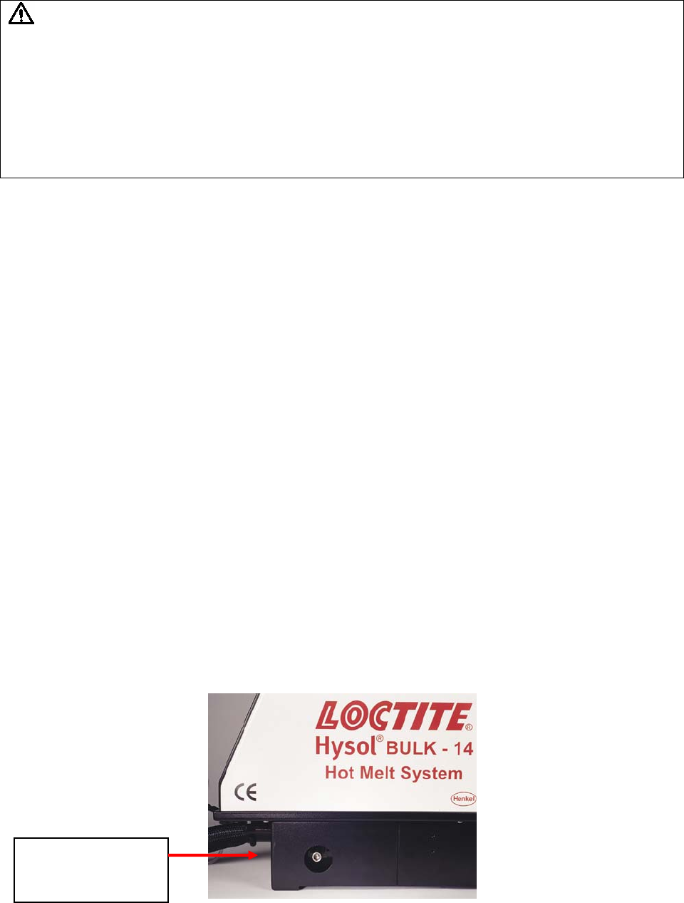
Figure 10
Pressure
Regulator Valve


