


20
Y1-03-0222 Rev. C
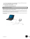
The GPS antenna has a free view through 360 degrees with a vertical angle of 5 to 90 degrees above
the horizon.
The GNSS antenna is placed as far away as possible from radar, Inmarsat and Iridium transmitters.
Also ensure that the GPS antenna is free from direct view of the radar and the Inmarsat beam. The
received GPS signal is very sensitive to noise and interference generated by other onboard
transmitters.
The MF/HF and other VHF transmitter antennas are kept as far away as possible from the GNSS
antenna. It is good practice never to install a GNSS antenna within a radius of 2 meters from these
antennas.
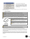
VHF antenna for AIS use
NOTE:
If you are installing a Class B AIS transponder on a vessel because you are required to do so, you must
use a separate VHF antenna and a separate GPS antenna dedicated to the Class B device in order to be
compliant with the regulations. Use the antennas supplied with this kit.
The VHF antenna supplied for use with the Nauticast™-B is omni-directional, vertically polarized with unity gain
(0 dB) and a band width sufficient to maintain VSWR <1.5 over the frequency range 156–163 MHz. As a
minimum the 3dB bandwidth will cover the two AIS channels and the DCS channel. The antenna is also suitable
for marine shipboard applications (index of protection, ruggedness, means of mounting, etc.).
If you elect to not use the antenna supplied, the alternate VHF antenna employed for AIS use:
Must be a dedicated antenna, i.e. not shared with any other VHF transmitter/receiver.
Should be mounted with at least a two meter vertical separation distance from any other VHF antenna
used for speech or DCS communication. Also see Appendix for warnings such as “Radio Frequency
Exposure Warning”.
SECTION 3 - USING THE TRANSPONDER
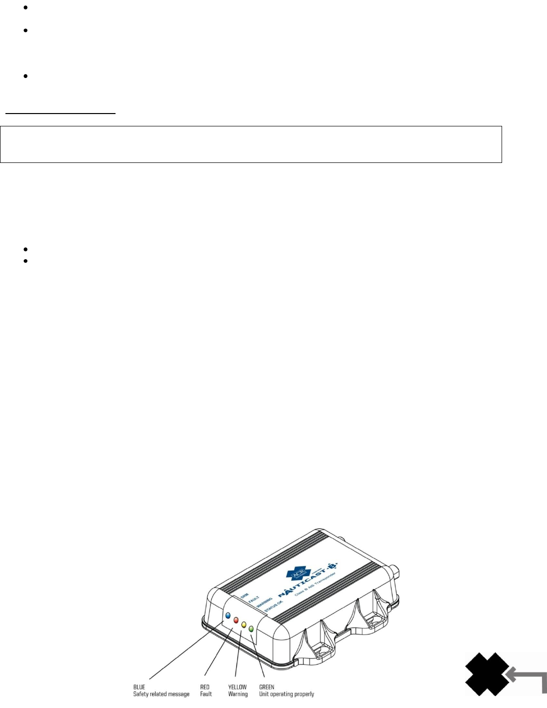
1. Switching ON
When the 12V supply is switched on, all four LEDs visible on the front panel of the unit will illuminate twice for a
period of one second on each illumination. The blue LED will then go out. When the internal GPS starts
outputting valid position information, the red LED will go out. When the Nauticast™-B AIS unit transmits its first
position report (message 18), the yellow LED will go out. Note that this process may take up to 30 minutes
depending on the switch-on state of the GPS receiver. When the yellow LED goes out the green LED will
illuminate indicating that the unit is now operating correctly.
2. Warning and fault states
If the unit has not been able to transmit a position report during the last expected two reporting intervals (i.e. the
nominal reporting interval cannot be maintained for operational reasons such as a Message 23 quiet period,
high channel load conditions, etc.) the yellow LED will illuminate. This is a warning condition only and indicates
that your vessel‟s position is not currently being reported to other vessels. Reception of other vessel AIS
information by the Nauticast™-B AIS is not affected. When the unit is able to commence reporting, the yellow
LED goes out.
If a fault occurs the red LED will illuminate. This may illuminate briefly if the power supply is interrupted or if the
VHF or GPS antenna characteristics are briefly affected.