


23
Y1-03-0222 Rev. C
Data
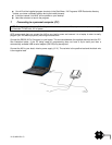
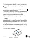
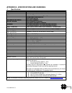
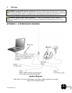
A minimum keypad and display (MKD) unit, chart plotter or other display device may be connected to the
Nauticast™-B AIS unit via the appropriate cable assembly. The default baud rate of the data link is 38.4k
baud with 8 data bits, one stop bit and no parity.
The data interface conforms to IEC 61162-1.
VDM, VDO, ACA, ACS, ALR, TXT and ACK messages conform to NMEA 0183. Please refer to NMEA 0183
for full details of these AIS messages.
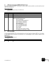
2. Serial Port Input/Output
There is one 9-pin serial port for data in RS232 format. There is one set of flying leads for data in RS422 format.
Duplex capability is available from either or both ports.
The serial port interface(s) output:
At power-up, boot-loader and main application splash text screens including version numbers and
memory status.
As a VHF Data Link Message (VDM) all incoming VHF Data Link (VDL) data received by the
Nauticast™-B AIS.
The VHF data link own vessel (VDO) messages sent by the Nauticast™-B AIS over the VHF Data Link.
AIS regional channel assignment messages (ACA) received. These are derived from an incoming VHF
Data Link message (message 22) or a DSC message.
AIS channel management information source (ACS) messages.
Alarm messages (ALR, TXT).
The data interface will accept:
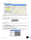
Personality programming messages
Alarm acknowledgement messages (ACK)
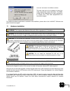
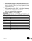
3. Power up messages
On power up, the unit will report details of the firmware versions residing in the unit.
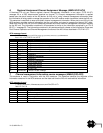
4. VHF data link messages (NMEA 0183 VDM)
This sentence is used to transfer the receipt of a VHF Data Link (VDL) message on either AIS radio channel, as
defined in ITU-R M.1371, using the “Six-bit” field type. The structure provides for the transfer of long binary
messages by using multiple sentences. Data messages should be transmitted in as few sentences as possible.
When a data message can be accommodated in a single sentence, it is not split.
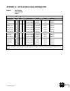
VDM message format
!--VDM,x1,x2,x3,a,s--s,x*hh<CR><LF>
field 1 2 3 4 5 6
Field
Format
Description
1
x
Total number of sentences needed to transfer the message
1
, 1 to 9
2
x
Sentence number
1
, 1 to 9
3
x
Sequential message identifier
2
, 0 to 9
4
a
AIS Channel, "A" or "B"
3
5
s---s
Encapsulated ITU-R M.1371 radio message
4
6
x
Number of fill-bits
5
, 0 to 5
NOTE 1 The length of an ITU-R M.1371 message may require the transmission of multiple sentences. The first
field specifies the total number of sentences used for a message, minimum value 1. The second field
identifies the order of this sentence in the message, minimum value 1. These cannot be null fields.