


38 ASUS A7V133 User’s Manual
Connectors
3. H/W SETUP
3. HARDWARE SETUP
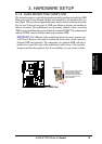
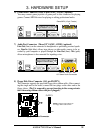
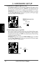
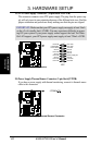
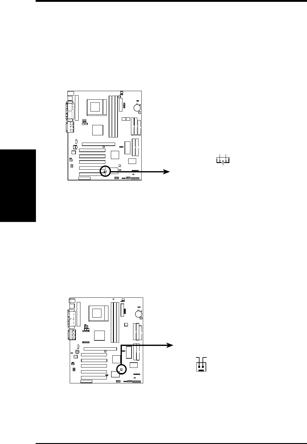
12) Wake-On-LAN Connector (3-pin WOL_CON)
This connector connects to a LAN card with a Wake-On-LAN output, such as
the ASUS PCI-L101 Ethernet card (see 7. Appendix). The connector powers up
the system when a wakeup packet or signal is received through the LAN card.
IMPORTANT: This feature requires that Wake-On-LAN features are enabled
(see 4.4.3 Power Management) and that your system has an ATX power supply
with at least 720mA +5V standby power.
01
01
01
A7V133
A7V133 Wake-On-LAN Connector
IMPORTANT: Requires an ATX power
supply with at least 720mA +5 volt
standby power
WOL_CON
+5 Volt Standby PME
Ground
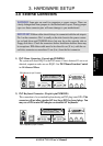
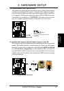
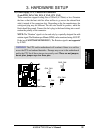
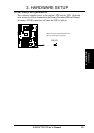
13) Wake-On-Ring Connector (2-pin WOR)
This connector connects to internal modem cards with a Wake-On-Ring output.
The connector powers up the system when a ringup packet or signal is received
through the internal modem card. NOTE: For external modems, Wake-On-Ring
is detected through the COM port.
IMPORTANT: This feature requires that Wake-On-Ring features are enabled
(see 4.4.3 Power Management) and that your system has an ATX power supply
with at least 720mA +5V standby power.
A7V Wake-On-Ring Connector
WOR
Ring#
Ground
2
1
0 1
0 1
0 1
A7V