


42 ASUS A7V133 User’s Manual
Connectors
3. H/W SETUP
3. HARDWARE SETUP
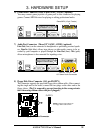
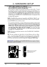
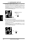
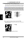
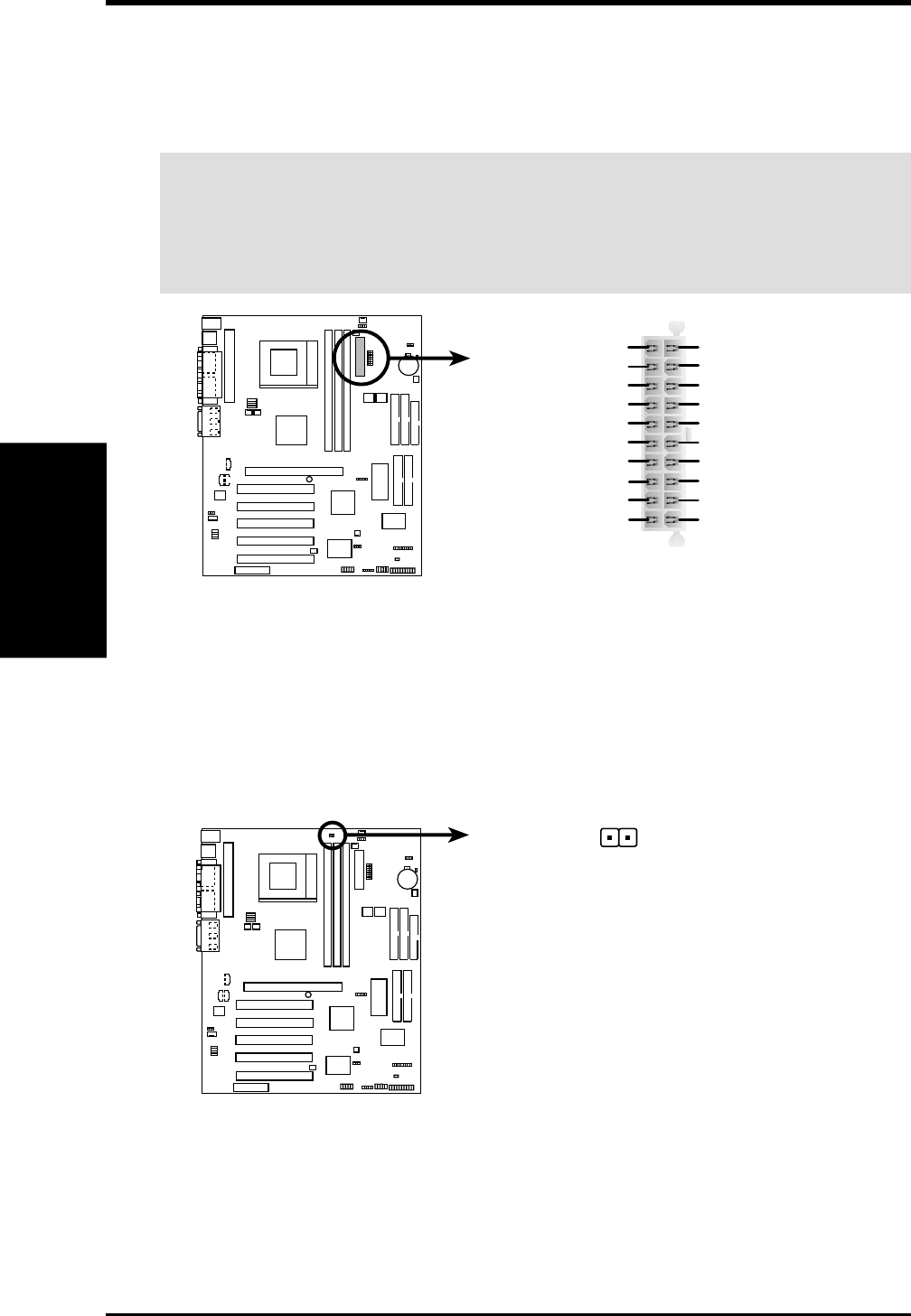
19) ATX Power Supply Connector (20-pin block ATXPWR)
This connector connects to an ATX power supply. The plug from the power sup-
ply will only insert in one orientation because of the different hole sizes. Find the
proper orientation and push down firmly making sure that the pins are aligned.
IMPORTANT: Make sure that your ATX power supply can supply at least 10mA
on the +5-volt standby lead (+5VSB). You may experience difficulty in power-
ing ON your system if your power supply cannot support the load. For Wake-
On-LAN support, your ATX power supply must supply at least 720mA +5VSB.
01
01
01
A7V133
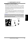
A7V133 ATX Power Connector
ATX
+3.3Volts
-12.0Volts
Ground
Power Supply On
Ground
Ground
Ground
-5.0 Volts
+5.0 Volts
+5.0 Volts
Power Good
+12.0Volts
+3.3 Volts
+3.3 Volts
Ground
+5.0 Volts
Ground
+5.0 Volts
Ground
+5V Standby
01
01
01
A7V133
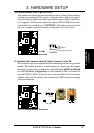
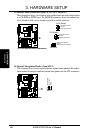
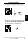
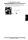
A7V133 Power Supply Thermal Sensor Connector
JTPWR
20) Power Supply Thermal Sensor Connector (2-pin block JTPWR)
If you have a power supply with thermal monitoring, connect its thermal sensor
cable to this connector.