


2-36
Chapter 2: Hardware information
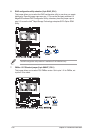
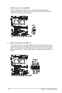
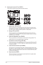
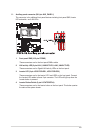
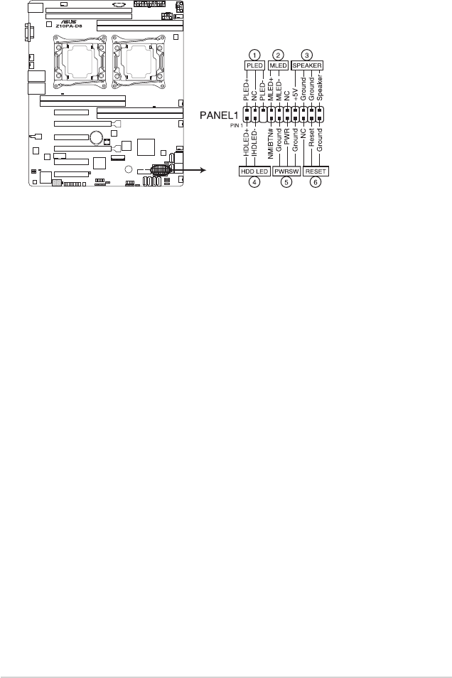
10. System panel connector (20-1 pin PANEL1)
This connector supports several chassis-mounted functions.
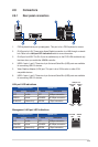
1. System power LED (3-pin PLED)
This3-pinconnectorisforthesystempowerLED.Connectthechassispower
LEDcabletothisconnector.ThesystempowerLEDlightsupwhenyouturnon
thesystempower,andblinkswhenthesystemisinsleepmode.
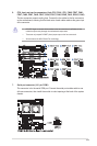
2. Message LED (2-pin MLED)
This2-pinconnectorisforthemessageLEDcablethatconnectstothefront
messageLED.ThemessageLEDiscontrolledbyHardwaremonitortoindicate
an abnormal event occurance.
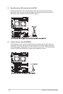
3. System warning speaker (4-pin SPEAKER)
This 4-pin connector is for the chassis-mounted system warning speaker. The
speaker allows you to hear system beeps and warnings.
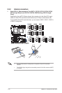
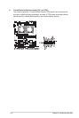
4. Hard disk drive activity LED (2-pin HDD LED)
This2-pinconnectorisfortheHDDActivityLED.ConnecttheHDDActivityLED
cabletothisconnector.TheHDLEDlightsuporasheswhendataisreadfrom
orwrittentotheHDD.
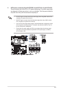
5. Power button/soft-off button (2-pin PWRSW)
This connector is for the system power button. Pressing the power button turns
thesystemonorputsthesysteminsleeporsoft-offmodedependingontheBIOS
settings. Pressing the power switch for more than four seconds while the system
is ON turns the system OFF.
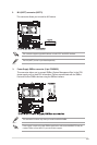
6. Reset button (2-pin RESET)
This 2-pin connector is for the chassis-mounted reset button for system reboot
without turning off the system power.