


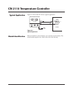
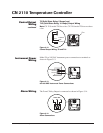
CN 2110
Omega
6
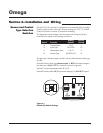
Section 3–Installation and Wiring
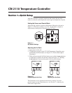
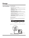
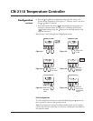
Figure 3.3
Mounting Dimensions
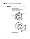
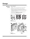
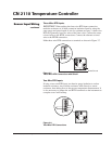
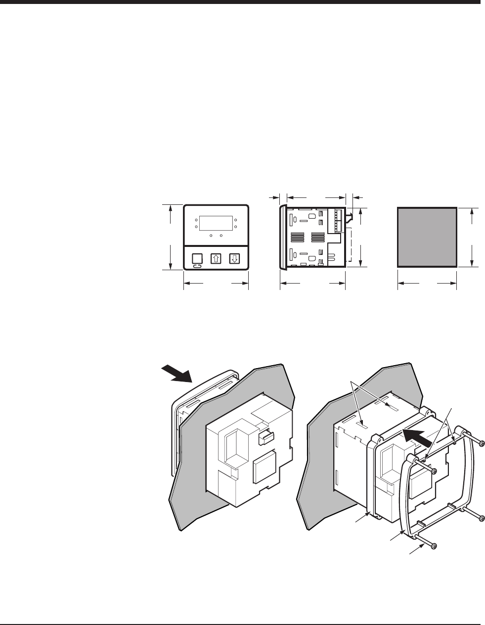
Figure 3.4
Mounting the 2110
Mount the CN 2110
1. Cut out a 1/4 DIN, 3.6-inch (92mm) square hole in the mounting
panel.
2. Insert the unit into the mounting hole as shown in Figure 3.4.
3. Slide the front mounting collar onto the back of the controller.
4. Slide the rear mounting collar onto the back of the controller until the
holding tabs securely engage with the holding tab slots in the control-
ler housing (see Figure 3.4).
5. Tighten the four rear collar mounting screws until the unit is held
firmly in the panel.
CAUTION: Do not overtighten.
The controller will now be held firmly in place.
Load
Alarm
°F
°C
Tem p
Set
Point
Set Point
Chromalox
®
2110
4.0
(101.6)
4.0
(101.6)
4.0
(102)
3.6
(92)
3.6
(92)
3.55
(90)
3.6
(92)
0.4
(10)
0.5
(12.7)
Panel
Cutout
Front Collar
Rear Collar
Rear Collar
Mounting
Screw
Holding
Tabs
Holding
Tabs Slots
Mounting
continued