


CN 2110 Temperature Controller
CN 2110
Table of Contents
1–Quick Setup ................................................................................................... 1
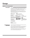
2–Introduction ................................................................................................... 2
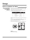
3–Installation and Wiring .................................................................................. 4
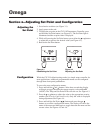
4–Adjusting Setpoint and Configuration ......................................................... 12
5–Controller and Alarm Operation .................................................................. 16
6–Replacing Output Modules .......................................................................... 17
7–Calibration ................................................................................................... 19
8–Specifications .............................................................................................. 21
9–Troubleshooting ........................................................................................... 22
10–Omega Warranty and Return ..................................................................... 24
Manual Sections
Illustrations
iii
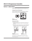
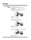
1.1 Dip Switch Settings .................................................................................. 1
1.2 Establishing the Set Point ......................................................................... 1
1.3 Adjusting the Set Point ............................................................................. 1
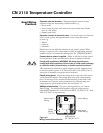
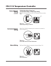
2.1 Front Panel Identification ......................................................................... 2
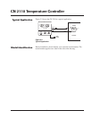
2.2 Typical Application .................................................................................. 3
2.3 Model Identification ................................................................................. 3
3.1 Default Dip Switch Settings ..................................................................... 4
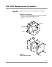
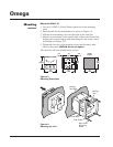
3.2 Removing Mounting Collars .................................................................... 5
3.3 Mounting Dimensions .............................................................................. 6
3.4 Mounting the CN 2110 ............................................................................. 6
3.5 Wiring Terminal Identification ................................................................. 7
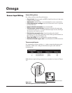
3.6 Thermocouple Connections with Shield .................................................. 8
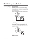
3.7 Three-Wire RTD Connections with Shield............................................... 9
3.8 Two-Wire RTD Connections .................................................................... 9
3.9 Control Output Wiring–R1 and TI.......................................................... 10
3.10 Control Output Wiring–R20 ................................................................... 10
3.11 Control Output Wiring–DC .................................................................... 10
3.12 Control Output Wiring–T5 and T10 ....................................................... 11
3.13 90-260 VAC Instrument Power Connections ......................................... 11
3.14 Alarm Connections ................................................................................. 11
4.1 Establishing the Set Point ....................................................................... 12
4.2 Adjusting the Set Point ........................................................................... 12
4.3 Configuring CN 2110 ............................................................................. 13
4.4 Configuring CN 2110 ............................................................................. 13
4.5 Configuring CN 2110 ............................................................................. 13
4.6 Configuring CN 2110 ............................................................................. 13
4.7 Configuring CN 2110 ............................................................................. 13
4.8 Configuring CN 2110 ............................................................................. 13
6.1 Replacing Output Module ...................................................................... 18