


CN 2110 Temperature Controller
CN 2110
7
Good Wiring
Practices
Separate wire into bundles—When planning the system wiring,
separate wiring into functionally similar bundles, e.g.
• Power leads
• Sensor leads (if power leads must cross sensor leads, they should
cross at a 90° angle)
• Output signal lines
Separate sources of electrical noise—Locate all sources of electrical
noise in your system, and separate these sources from the control
system, e.g.
• Motors
• Contacts
• Solenoids
Electrical noise can affect the function of any control system. When
driving a contactor coil or other inductive load, an appropriate rated AC
snubber circuit is recommended (Omega Part No. CNQUENCHARC).
Connect before power is applied—Make all electrical wiring connec-
tions to the back of the controller before power is applied to the unit.
Comply with regulations—WARNING: All wiring practices must
comply with local regulations. Failure to do so could result in damage
to controller and/or personal injury or death from electrical shock.
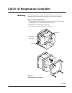
This instrument is intended for panel mounting and the terminals must
be enclosed within a panel. Use National Electric Code (NEC) Class 1
wiring for all terminals except the sensor terminals.
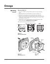
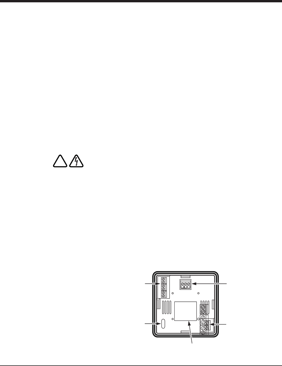
Check wiring decal—Check the wiring decal on the side of the unit to
verify the model number. The wiring decal shows the wiring termina-
tions. All wiring will be connected to the terminals on the back of the
instrument case. Specific wiring instructions for different input and
output types are given in this section. See also Figure 3.5.
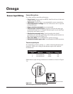
Additional information—For sensor wiring practices, see “Sensor
Input Wiring”. For additional information on good wiring practice,
request IEEE Standard No. 518-1982 from IEEE, 345 East 47
th
St., New
York, NY 10017 or www.ieee.org.
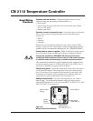
Figure 3.5
Wiring Terminal Identification
!
NC
NO
COM
Sensor Input
Wiring
Output
Wiring
(T5, T10)
Output Wiring
(R1, R20, DC, or T1)
Instrument
Power Wiring
Alarm Wiring
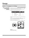
Section 3–Installation and Wiring