


Dell
PowerEdge R210 Technical Guide 23
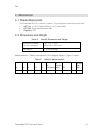
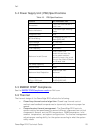
Table 7. TPM Pin Signals
Pin SIGNAL Pin SIGNAL
1 TPM_PRES_N 20 I2C_TPM_SCL
2 LPC_LAD0 19 P3V3
3 GND 18 I2C_TPM_SDA
4 LPC_LAD1 17 LPC_LAD3
5 SEEPROM I2C Address E0 16 GND
6 P3V3_AUX 15 SERIRQ
7 RST_TPM_R_N 14 P3V3
8 LPC_LFRAME_N 13 LPC_LAD2
9 GND 12 GND
10 TPM 33MHz Clock 11 TPM 14MHz Clock
4.12.4 Power Switch Security
The LED control panel is designed so the power switch cannot be accidentally turned
on or off. In addition, in BIOS there is an optional setting in the CMOS setup to disable
the power switch.
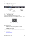
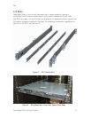
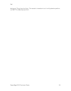
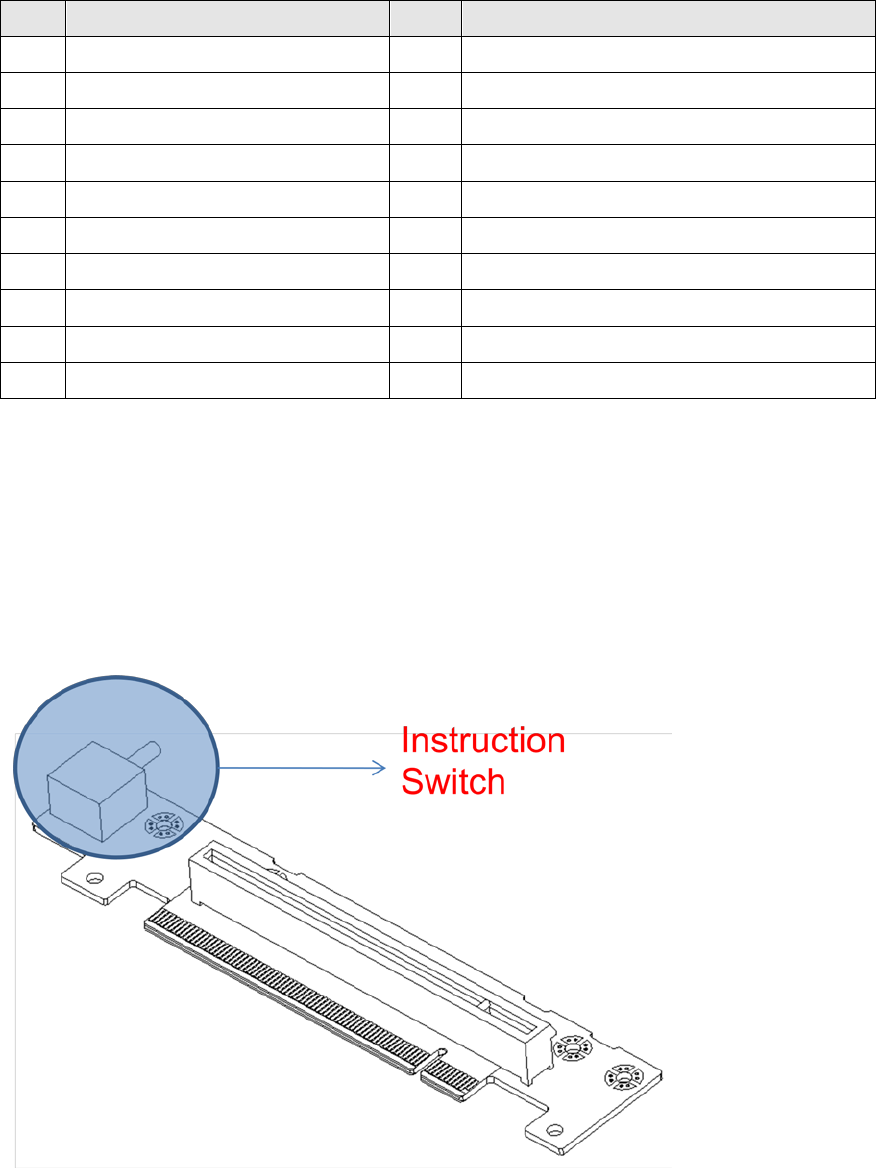
4.12.5 Intrusion Alert
The intrusion switch snaps into the chassis located under the side cover. The intrusion
switch detects and alerts the user that the side cover is open.
Figure 10. Intrusion Switch