


OCT 2013 DANIEL™ SERIES 1500 TURBINE METER
INSTALLATION3-4
MECHANICAL EQUIPMENT DAMAGE
Always use a flushing medium that is compatible with the metallurgy of the meter and
its internal components and similar to the product for which the meter is intended.
Using water as a flushing medium may result in damage to the internal components of the
turbine meter.
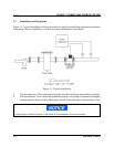
A. Valves
The metering system should have a flow rate control valve located at a convenient distance
downstream of all measurement equipment. The function of the control valve is to limit and maintain
system pressure on the meter. This avoids cavitation.
1. Valves should be capable of rapid, smooth opening and closing with positive shut-off.
2. When used for intermittent flow, valves should be fast acting and shock-free.
3. Bypass lines should be equipped with blind or positive shutoff devices.
4. Shut-off or control valves should be located downstream of the meter.
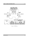
B. Flow Conditioning
For proper operation flow conditioning is required on both the upstream and downstream sides of
the meter.
On the upstream side of the meter a flow conditioning plate can be used (see paragraph C, Flow
Conditioning Plate) or a flow conditioning element designed in accordance with API Ch.5.3. This
element should be installed in an upstream section of pipe having a minimum length equal to 10 pipe
diameters.