


1. INSTALLATION
1-14
Tools and materials needed
Scissors
Masking tape
Safety goggles
Dust mask
Electric drill
Drill bit for:
Bracket holes: 4mm, #23, or 9/64”
Fiberglass hull: chamfer bit (preferred),
6mm, or 1/4”
Transom hole: 19mm or 3/4” (optional)
Cable clamp holes: 3mm or 1/8”
Screwdrivers
Straight edge
Marine sealant
Pencil
Zip-ties
Water-based antifouling paint (mandatory in salt water).
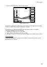
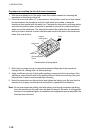
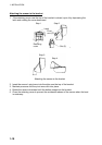
Mounting location
To ensure the best performance, the sensor must be submerged in aeration-free and
turbulence-free water. Mount the sensor close to the centerline of the boat. On slower
heavier displacement hulls, positioning it farther from the centerline is acceptable.
Allow adequate space above the bracket for it to release and rotate the sensor upward.
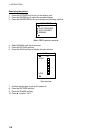
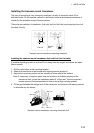
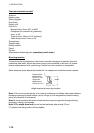
Height
Height without
speed sensor
191mm (7-1/2")
Height with
speed sensor
213mm (8-1/2")
Height required at mounting location
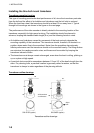
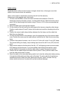
Note 1: Do not mount the sensor in an area of turbulence or bubbles: near water intake or
discharge openings; behind strakes, struts, fittings, or hull irregularities; behind eroding
paint (an indication of turbulence).
Note 2: Avoid mounting the sensor where the boat may be supported during trailering,
launching, hauling, and storage.
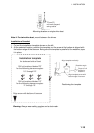
Note 3: For single drive boat, mount on the starboard side at least 75 mm
(3”) beyond the swing radius of the propeller.