


1. INSTALLATION
1-16
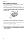
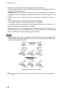
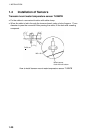
3. Using a 4 mm, #23, or 9/64” bit, drill three holes 22 mm (7/8”) deep
at the locations indicated. To prevent drilling too deeply, wrap masking tape around the
bit 22 mm (7/8”) from the point.
Fiberglass hull: Minimize surface cracking by chamfering the gelcoat. If a chamfer bit
or countersink bit is not available, start drilling with a 6mm or 1/4” bit to a depth of 1 mm
(1/16”).
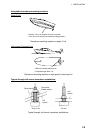
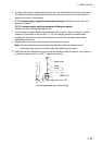
4. If you know your transom angle, the bracket is designed for a standard 13° transom
angle.
11°-18° angle: No shim is required. Skip to step 3 in “Adjusting”.
Other angles: The shim is required. Skip to step 2 of “Adjusting”.
If you do not know the transom angle, temporarily attach the bracket and sensor to the
transom to determine if the plastic shim is needed.
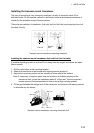
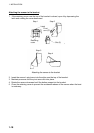
5. Using the two #10 x 1-1/4” self-tapping screws, temporarily screw the bracket to the hull.
DO NOT tighten the screws completely at this time. Follow the step 1-4 in “Attaching the
Sensor to the Bracket”, before proceeding with “Adjusting”.
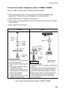
Adjusting
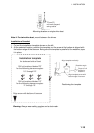
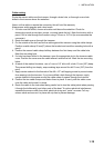
1. Using a straight edge, sight the underside of the sensor relative to the underside of the
hull. The stern of the sensor should be 1-3 mm (1/16-1/8”) below the bow of the sensor
or parallel to the bottom of the hull.
11° transom angle
NO SHIM
12-18° transom angle
NO SHIM
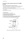
2°-10°
transom
angle
19°-22°
transom
angle
shim with
taper up
shim with
taper down
parallelparallel parallel
slight
angle
angle
too steep
angle
reversed
YES NO
NO
YES YESYES
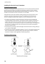
Sensor position and transom angle
Note: Do not position the bow of the sensor lower than the stern because aeration will
occur.