


2-8
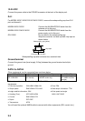
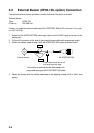
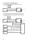
2.5 Connection of CU-200 (option)
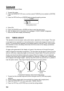
1) Connection between one display unit and one memory card IF unit
Connect as shown in the figure below.
Display unit
Memory card IF unit
CU-200
NETWORK
12 VDC
NETWORK
MJ-A15A3F0003-030 (3 m, supplied)
MJ-A6SPF/TM11AP8-C050 (5 m,supplied)
two mini-cards
12 VDC
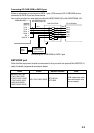
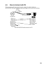
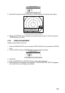
2) Connection between one memory card IF unit and multiple processor units
Prepare optional cable MJ-A6SPF0014-010/050/100/200/300 (1, 5, 10, 20 or 30 m) and
MJ-A6SRM-D/TM 11AP8-005. Also, procure HUB and CAT5 STP cable locally. Connect as
shown in the figure below.
No.1
Display
unit
NETWORK
No.2
Display
unit
No.3
Display
unit
No.4
Display
unit
MJ-A15A3F0003-030 (3 m, supplied)
Memory card IF unit
12 VDC
NETWORK
MJ-A6SPF0014-010/050/
100/200/300 (cross)
CAT5 STP cable
(local supply)
HUB
(owner supply)
two mini-cards
MJ-A6SRMD/TM11AP8-005
MJ-A6SPF0014-010/050/100/200/300
MJ-A6SPF0014-010/050/100/200/300
MJ-A6SPF0014-010/
050/100/200/300
12 VDC