


4-6
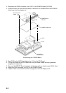
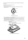
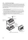
4. Set two cable tie “legs” (supplied with option kit) as shown below.
Cable ties attachment.
5. Tie the connector assy with two cable ties attached at step 4.
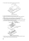
6. Remount the POWER Board and power shield case with pan head screws (M3x8, 5
pcs.)
7. Attach the PH5P connector from SPU Board to J1357 on the POWER Board.
8. Pass the connector assy through the saddle on the POWER Board.
9. Remount the display unit cover referring to the illustration on page 4-3 so that the cable
runs through the hole the connector cover removed.
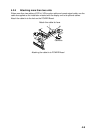
10. Cut a “cross” in the grommet to pass the cable through it and then attach the grommet.
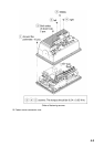
Display unit, passing the PIP cable
11. Fasten the ground wire of the connector assy with a pan head screw (M4x10) shown in
the above. Finally, cover the hole with soft putty to seal