


4-7
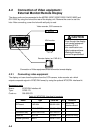
4.2.2 Connecting external monitor
You can display the MODEL1823C/1833C/1933C/1943C screen on the external monitor,
which accepts industrial standard VGA input by using the optional RGB output cable kit
OP03-176. Supply monitor and interconnection cable (with HD-15P connectors of male,
three rows of 15 pins) locally.
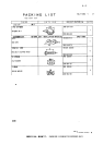
Necessary parts for external monitor
Name: RGB output cable kit
Type: OP03-176
Code No.: 008-526-360
Name Type Code No. Qty
Cable assy. 15SDS/XHP10-005 000-144-511 1
Grommet MG-4 000-871-378 1
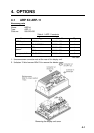
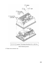
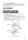
1. Unscrew 15 binding screws (M3x10, w/nylon washer) and seven connector nuts to
remove the display unit cover.
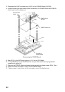
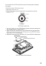
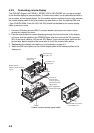
2. Cut a “cross” in the grommet (to pass the cable).
3. Pass the RGB output cable through the grommet hole at the rear of the display unit
cover and the saddle on the POWER Board, and then connect the XH connector (10P)
of the RGB output cable to J110 on the SPU Board. Put the ground wire of the cable
outside of the cover.
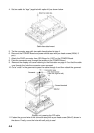
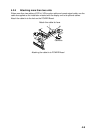
4. Reassemble the display unit referring to the illustration on page 4-3.
5. Fix the ground wire of the cable with one of two screws both sides of the connector hole.
6. Finally, cover the hole with soft putty to seal
How to connect 15SDS/XHP10-005