


4-2
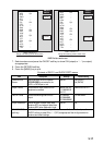
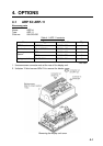
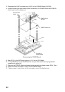
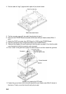
3. Disconnect the PH5P connector from J1357 on the POWER Board (19P1005).
4. Unfasten seven pan head screws (M3x8) to dismount the POWER Board and POWER
shield case from the display unit.
To J1357 on
POWER Board
POWER shield case
POWER Board
19P1005
Pan head screws
(M3x8) 7 pcs.
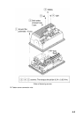
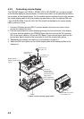
SPU Board
ARP Board
J1357
P107
J112
Dismounting the POWER Board
5. Mate P107 on the ARP Board (option) to J112 on the SPU Board.
6. Fix the ARP Board on the SPU Board with four pan head screws and spring washers
(supplied with option kit).
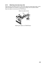
7. Remount the POWER Board and power shield case with pan head screws (M3x8, 7pcs.)
8. Attach the PH5P connector to J1357 on the POWER Board.
9. Fasten screws in order shown on the next page to mount the display cover.