


2-1
2. WIRING
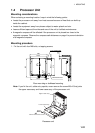
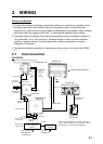
Wiring consideration
• To lessen the chance of picking up electrical interference, avoid where possible routing
the signal cable near other onboard electrical equipment (radars, transmitting radio
antennas, etc.) Also avoid running the cable in parallel with power cables. When crossing
with other cable, the angle should be 90°to minimize the magnetic field coupling.
• The signal cable run between the antenna and processor units is available in lengths of
15 m (standard), 30 m, 40 m and 50 m. Whatever length is used it must be unbroken;
namely, no splicing allowed. Use the signal cable as short as possible to minimize
attenuation of the signal.
• The radar should be connected to an emergency power source, as required by SOLAS
II-1.
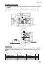
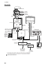
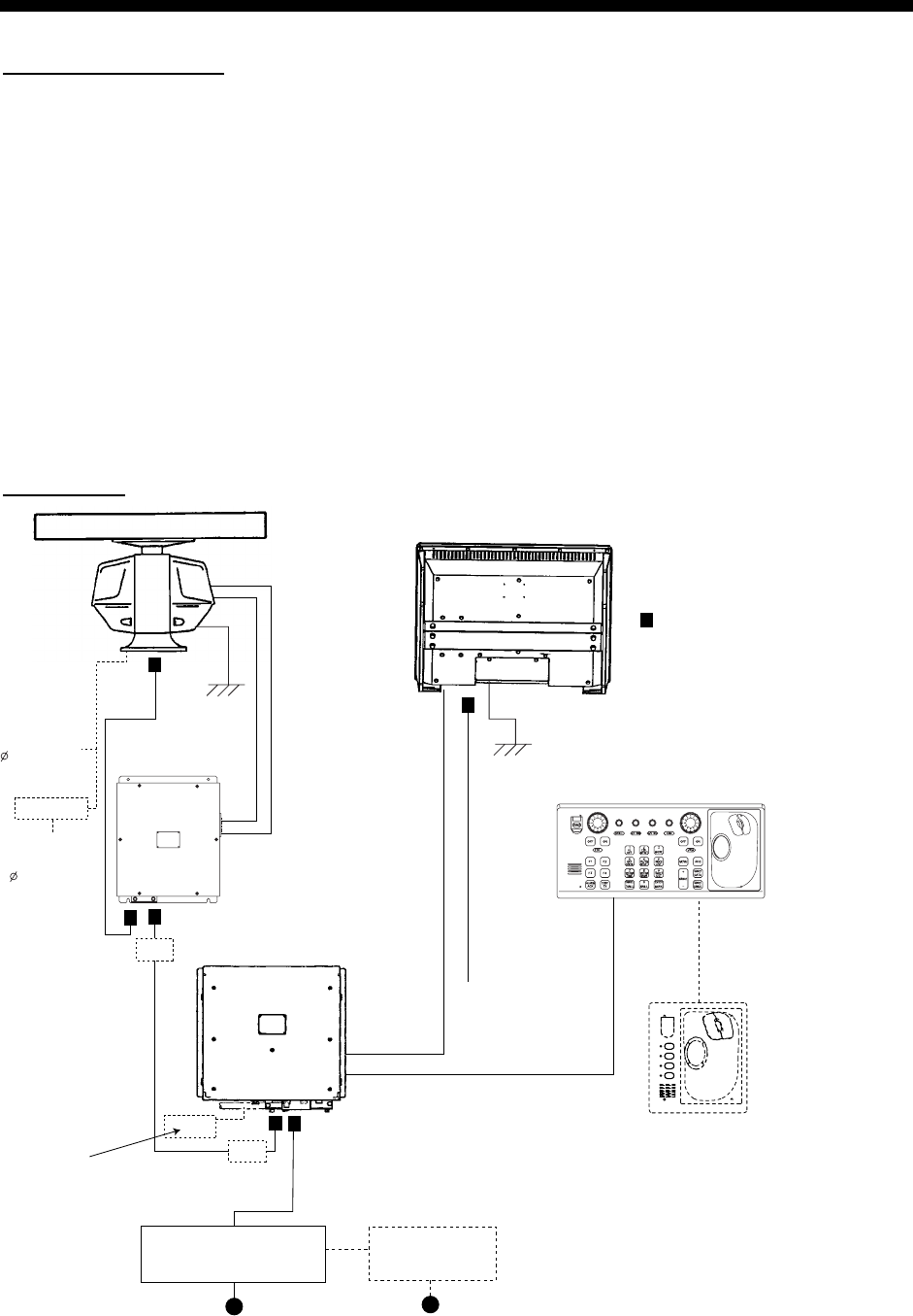
2.1 Interconnection
FAR-2827W
Processor unit
RPU-013
Antenna unit
TB803
Monitor unit
Control unit
(RCU-014 or RCU-015)
Antenna cable*
DPYC-2.5
XH10P-W-6P, 1.5/10/20/30 m
100-230 VAC
DVI-D/D SINGLE LINK 5M/10M
Waveguide
WRJ-9
or
FR-9
MPYCY-19
(Max. 30 m)
F4
F3
F2
F1
Control unit
(RCU-016)
TB803
TB801
Junction box
RJB-001*
Junction box
RJB-001*
Memory card I/F unit
CU-200-FAR
Transceiver
unit
RTR-081A
RU-3305
100 VAC,
1 , 50/60 Hz
110/115/
220/230 VAC,
1 , 50/60 Hz
For De-icer
XH10P-W-5P-A,
10/20/30 m
: Cable requires fabrication
*: If the length of the antenna cable is less than
100 m, use RW-9600. If it is more than 100 m,
see section 4.5 "Junction Box RJB-001".
AC spec
Russian flag
vessel only
DPYC-2.5
100-115 VAC/
220-230 VAC
1
φ, 50-60 Hz
Transformer Unit
RU-1803
440 VAC
1
φ, 50-60 Hz
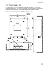
Power Supply Unit
PSU-011