


1. MOUNTING
1-6
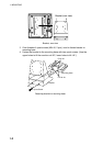
To mount the control unit separate from the monitor unit, the optional control unit
separate kit is required. Mount the control unit same as the above procedure.
See the outline drawing at the back of this manual to mount.
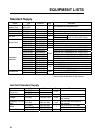
Type: OP06-15-1.5 NEW Code no.: 006-559-140: with 1.5 m cable
Type: OP06-15-5 NEW Code no.: 006-559-150: with 5 m cable
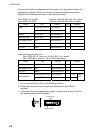
Name Type Code no. Qty Remarks
MJ-A10SPF0002-015 000-142-878 For 1.5 m cableCable
MJ-A10SPF0002-050 000-131-411
1
For 5 m cable
Bracket 06-021-2112 100-281-880-10 1
Mounting Plate 06-021-2111-1 100-279-741-10 1
Self-tapping Screw 5x20 000-162-608-10 2
Cosmetic Cap DP-687 000-165-997-10 2
Hex. bolt M4x12 000-162-939-10 4
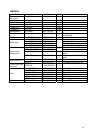
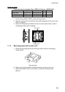
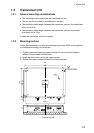
Flush mounting for control unit
Type: OP02-83-1.5, Code no.: 001-413-600 (1.5 m cable)
Type: OP03-83-5, Code no.: 001-413-610 (5m cable)
Name Type Code No. Qty Remarks
Fixing metal 06-021-2101-2 100-279-732-10 1
Self-tapping screw 5x20 000-162-609-10 4
Hex. bolt M4x12 000-162-939-10 2
MJ-A10SPF0002-015 000-142-878 1 1.5 m
Cable assembly
MJ-A10SPF0002-050 000-131-411 1 5 m
Select
one.
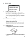
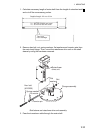
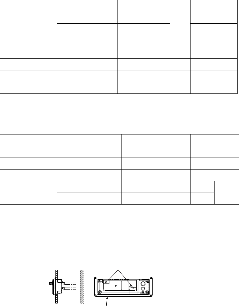
1. Cut out a hole (W287 x H87) in the mounting location.
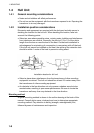
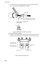
2. Fasten the fixing metal to the control unit with two hex. bolts (M4x12,
supplied).
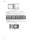
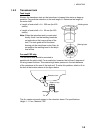
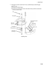
3. Fasten the fixing metal assembled at step 2 to holes made at step 1 with four
self-tapping screws (5x20, supplied).
Hex. bolts
Fixing metal